- Place the transfer case in a shallow pan and remove the fill (1) and drain (2) plugs to drain the remainder of the fluid. See Fig 1.
 Courtesy of DAIMLERCHRYSLER CORP.
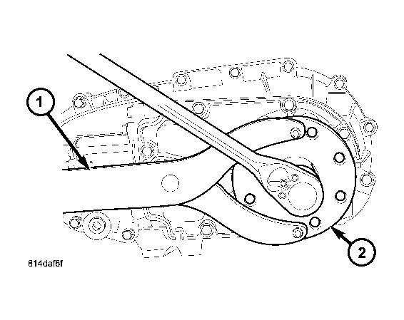
| 1 - HOLDER C-3281 |
| 2 - REAR COMPANION FLANGE |
- Using Holder C-3281 (1), remove the rear flange (2) nut. See Fig 2.
 Courtesy of DAIMLERCHRYSLER CORP.
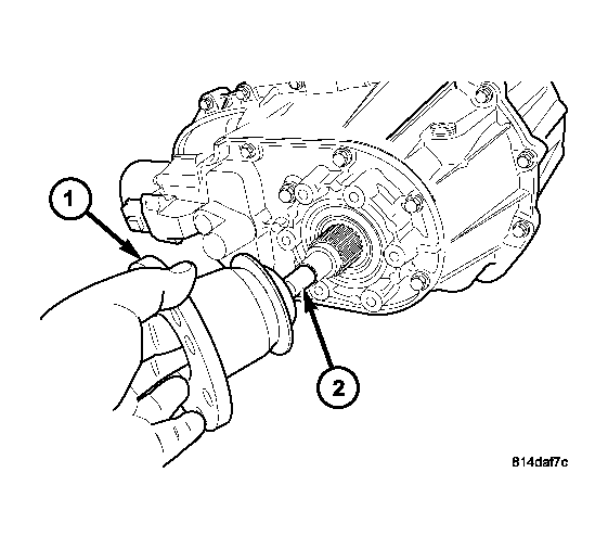
| 1 - REAR COMPANION FLANGE |
| 2 - OUTPUT SHAFT |
- Remove the rear output flange (1) from the main shaft (2). If necessary, use a suitable 2 or 3 jaw puller to remove the output flange. See Fig 3.
 Courtesy of DAIMLERCHRYSLER CORP.
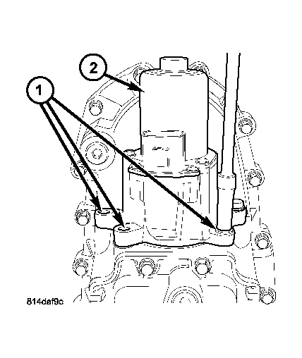
| 1 - BOLTS |
| 2 - SHIFT MOTOR AND MODE SENSOR ASSEMBLY |
- Remove the bolts (1) holding the shift motor and mode sensor assembly (2) to the transfer case. See Fig 4.
 Courtesy of DAIMLERCHRYSLER CORP.
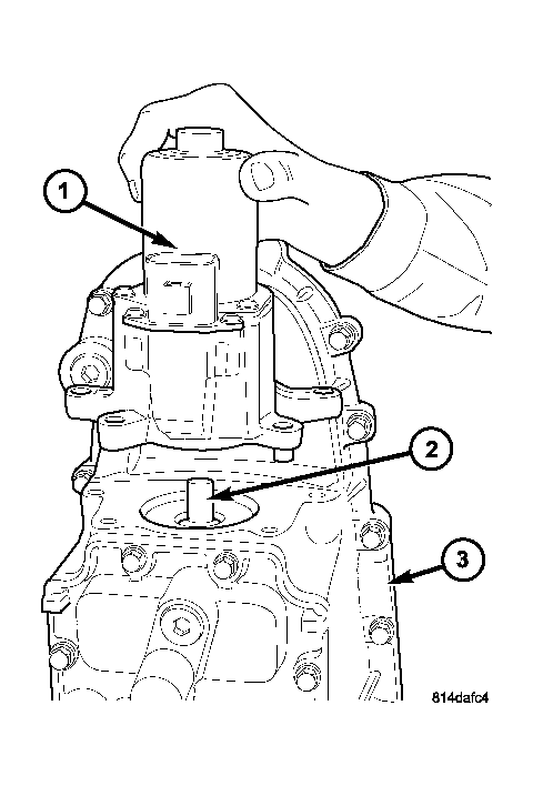
| 1 - SHIFT MOTOR AND MODE SENSOR ASSEMBLY |
| 2 - SHIFT SECTOR |
| 3 - TRANSFER CASE |
- Remove the shift motor and mode sensor assembly (1) from the shift sector (2) and the transfer case (3). See Fig 5.
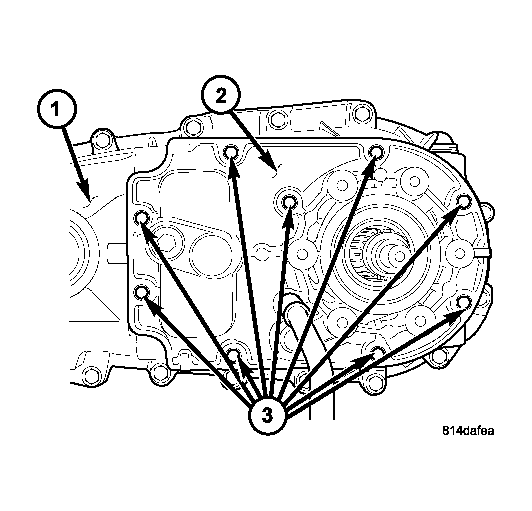 Courtesy of DAIMLERCHRYSLER CORP.
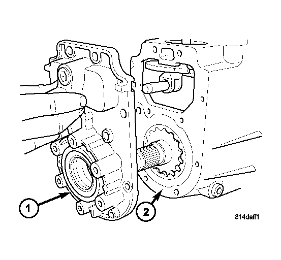
| 1 - REAR HOUSING |
| 2 - REAR COVER |
| 3 - BOLTS |
- If necessary, remove the bolts holding the transfer case damper to the transfer case and remove the damper.
- Remove the bolts (3) holding the rear cover (2) onto the rear housing (1). See Fig 6.
 Courtesy of DAIMLERCHRYSLER CORP.
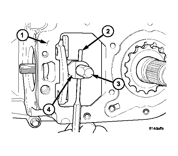
| 1 - REAR COVER |
| 2 - REAR HOUSING |
NOTE:
Use the pry slots provided and take care not to damage the sealing surface.
- Remove the rear cover (1) from the rear housing (2). See Fig 7.
 Courtesy of DAIMLERCHRYSLER CORP.
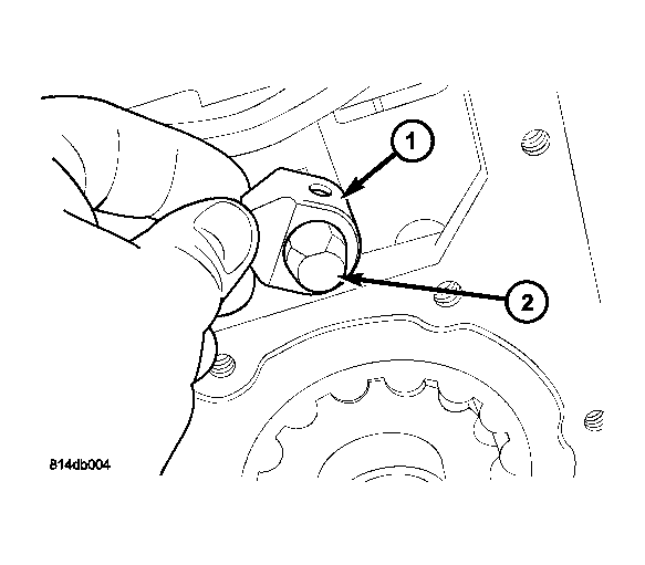
| 1 - REAR HOUSING |
| 2 - ROLL-PIN |
| 3 - SHIFT RAIL |
| 4 - SECTOR ROLLER |
NOTE:
Rotate the sector upward to ease the removal of the roll-pin.
- Using a suitable punch, remove the roll-pin (2) holding the sector roller (4) to the shift rail (3). See Fig 8.
 Courtesy of DAIMLERCHRYSLER CORP.
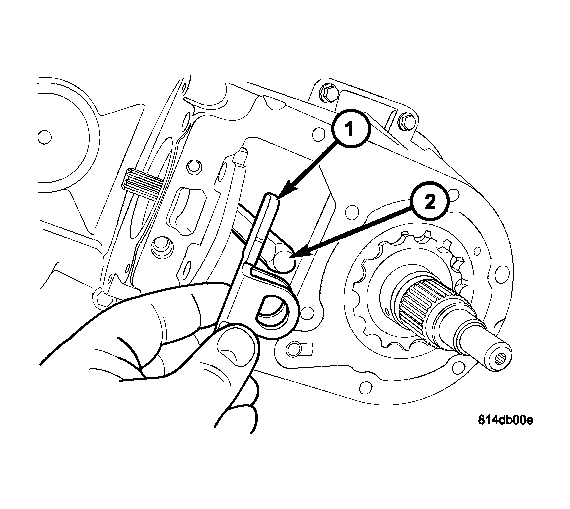
| 1 - SECTOR ROLLER |
| 2 - SHIFT RAIL |
- Remove the sector roller (1) from the shift rail (2). See Fig 9.
 Courtesy of DAIMLERCHRYSLER CORP.
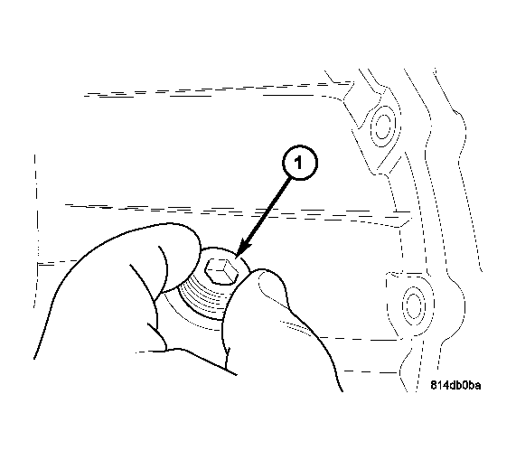
| 1 - ANTI-ROTATION BRACKET |
| 2 - SHIFT RAIL |
- Remove the anti-rotation bracket (1) from the shift rail (2). See Fig 10.
 Courtesy of DAIMLERCHRYSLER CORP.
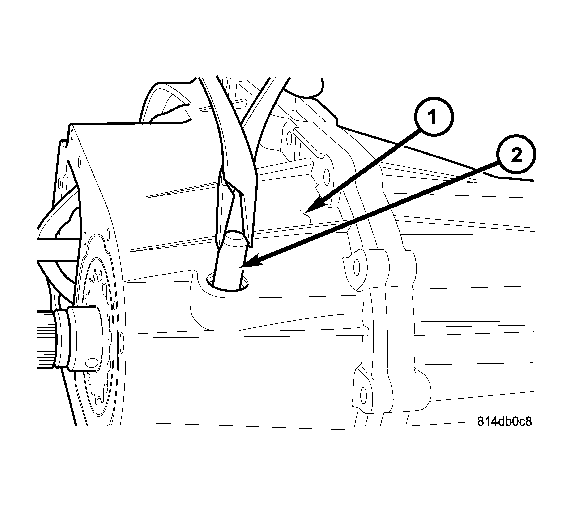
| 1 - CLUTCH LEVER RAIL PLUG |
- Remove the clutch lever rail plug (1) from the rear housing. See Fig 11.
 Courtesy of DAIMLERCHRYSLER CORP.
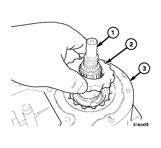
| 1 - REAR HOUSING |
| 2 - CLUTCH LEVER RAIL |
- Remove the clutch lever rail (2) from the rear housing (1). See Fig 12.
 Courtesy of DAIMLERCHRYSLER CORP.
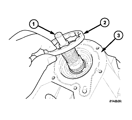
| 1 - OUTPUT SHAFT |
| 2 - OIL PUMP INNER ROTOR |
| 3 - REAR HOUSING |
- Remove the oil pump inner rotor (2) from the main shaft (1) and rear housing (3). See Fig 13.
 Courtesy of DAIMLERCHRYSLER CORP.
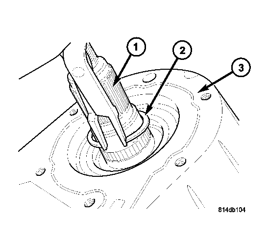
| 1 - OUTPUT SHAFT |
| 2 - OIL PUMP OUTER ROTOR |
| 3 - REAR HOUSING |
- Remove the oil pump outer rotor (2) from the main shaft (1) and rear housing (3). See Fig 14.
 Courtesy of DAIMLERCHRYSLER CORP.
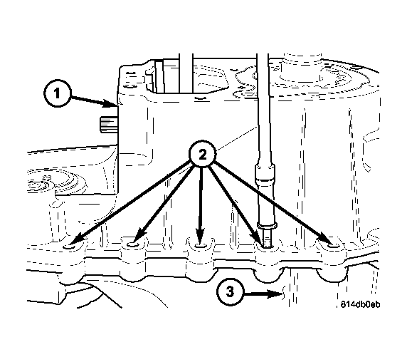
| 1 - OUTPUT SHAFT |
| 2 - RETAINING RING |
| 3 - REAR HOUSING |
NOTE:
Pull upward on the main shaft to ease the removal of the main shaft retaining ring.
- Remove the rear output shaft (1) retaining ring (2). See Fig 15.
 Courtesy of DAIMLERCHRYSLER CORP.
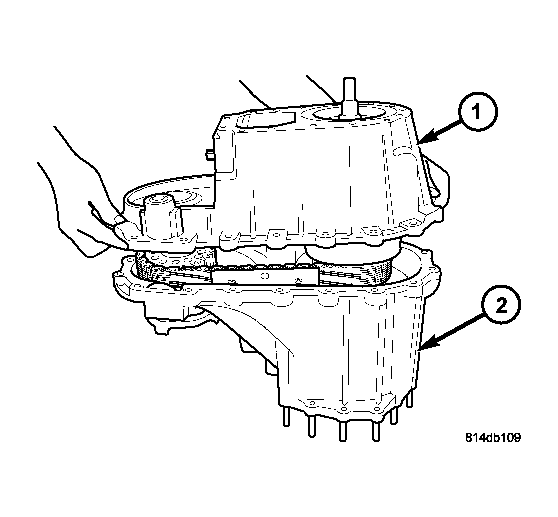
| 1 - REAR HOUSING |
| 2 - BOLTS |
| 3 - FRONT HOUSING |
- Remove the bolts (2) holding the rear housing (1) to the front housing (3). See Fig 16.
 Courtesy of DAIMLERCHRYSLER CORP.
| 1 - REAR HOUSING |
| 2 - FRONT HOUSING |
NOTE:
Some prying may be necessary to break the seal between the front and rear case. Use care to not damage the sealing surfaces.
- Remove the rear housing (1) from the front housing (2). See Fig 17.
 Courtesy of DAIMLERCHRYSLER CORP.
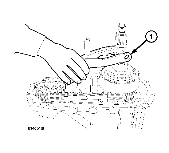
| 1 - CLUTCH LEVER ASSEMBLY |
- Remove the clutch lever assembly (1) from the mainshaft and shift rail. See Fig 18.
 Courtesy of DAIMLERCHRYSLER CORP.
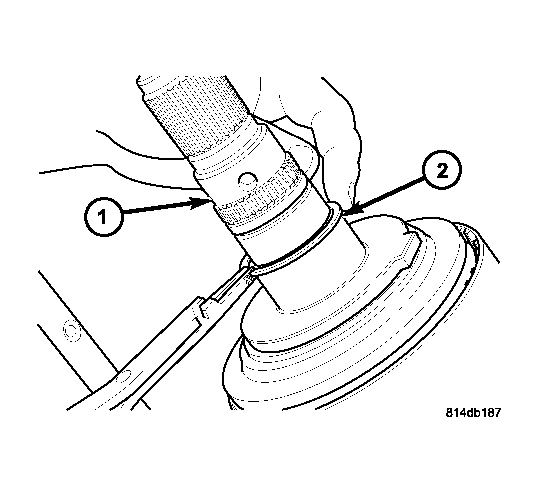
| 1 - OUTPUT SHAFT |
| 2 - RETAINING RING |
- Remove the thrust bearing support plate retaining ring (2) from the main shaft (1). See Fig 19.
 Courtesy of DAIMLERCHRYSLER CORP.
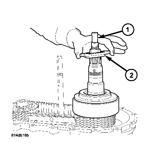
| 1 - OUTPUT SHAFT |
| 2 - SUPPORT PLATE |
- Remove the thrust bearing support plate (2) from the main shaft (1). See Fig 20.
 Courtesy of DAIMLERCHRYSLER CORP.
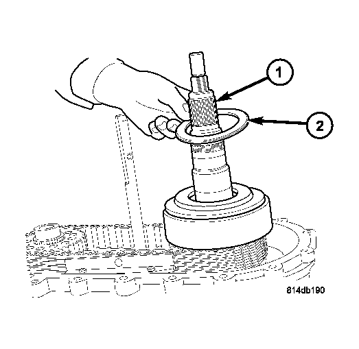
| 1 - OUTPUT SHAFT |
| 2 - THRUST BEARING |
- Remove the thrust bearing (2) from the main shaft (1). See Fig 21.
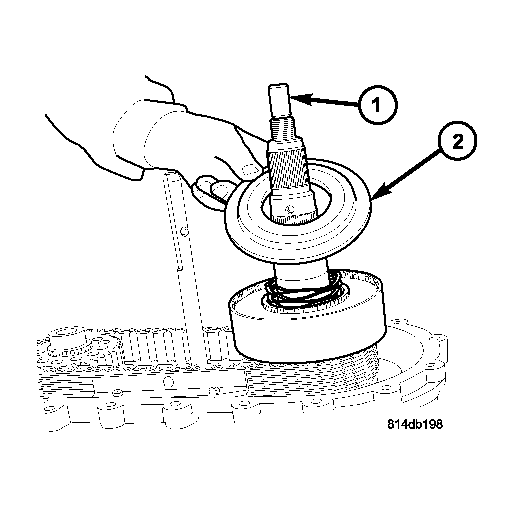 Courtesy of DAIMLERCHRYSLER CORP.
| 1 - OUTPUT SHAFT |
| 2 - CLUTCH PRESSURE PLATE |
- Remove the clutch pressure plate (2) from the main shaft (1) and clutch assembly. See Fig 22.
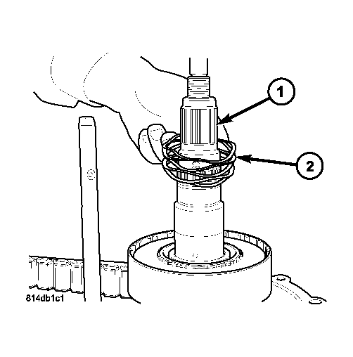 Courtesy of DAIMLERCHRYSLER CORP.
| 1 - OUTPUT SHAFT |
| 2 - WAVY SPRING |
- Remove the wave spring (2) from the main shaft (1). See Fig 23.
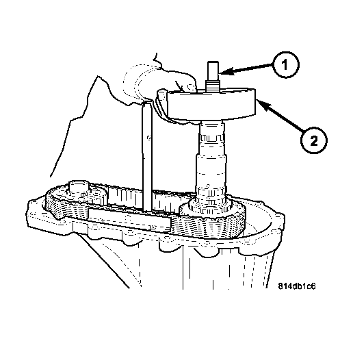 Courtesy of DAIMLERCHRYSLER CORP.
| 1 - OUTPUT SHAFT |
| 2 - CLUTCH ASSEMBLY |
- Remove the clutch assembly (2) from the main shaft (1). See Fig 24.
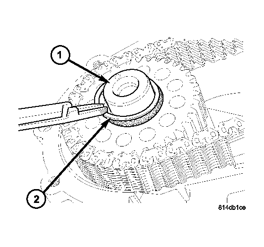 Courtesy of DAIMLERCHRYSLER CORP.
| 1 - FRONT OUTPUT SHAFT |
| 2 - RETAINING RING |
- Remove the front drive sprocket retaining ring (2) from the front output shaft (1). See Fig 25.
 Courtesy of DAIMLERCHRYSLER CORP.
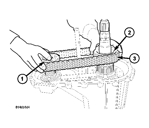
| 1 - FRONT DRIVE SPROCKET |
| 2 - MAINSHAFT DRIVE SPROCKET |
| 3 - DRIVE CHAIN |
- Remove the front drive sprocket (1), mainshaft drive sprocket (2), and drive chain (3) as one. See Fig 26.
 Courtesy of DAIMLERCHRYSLER CORP.
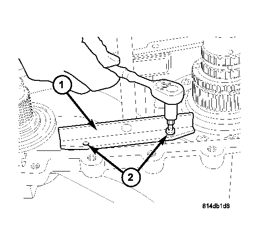
| 1 - CHAIN GUIDE RAIL |
| 2 - SCREWS |
- Remove the screws (2) holding the chain guide rails (1) to the front housing. See Fig 27.
 Courtesy of DAIMLERCHRYSLER CORP.
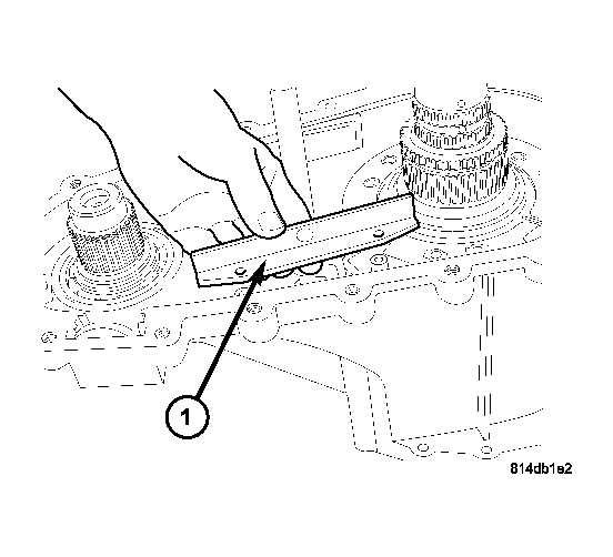
- Remove the drive chain guides (1) from the transfer case. See Fig 28.
 Courtesy of DAIMLERCHRYSLER CORP.
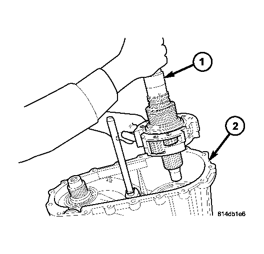
| 1 - MAINSHAFT AND DIFFERENTIAL ASSEMBLY |
| 2 - FRONT HOUSING |
- Remove the mainshaft and differential assembly (1) from the front housing (2). See Fig 29.
 Courtesy of DAIMLERCHRYSLER CORP.
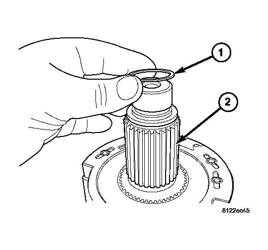
| 1 - SNAP-RING |
| 2 - INTERMEDIATE CLUTCH SHAFT |
- Remove intermediate clutch shaft (2) snap-ring (1). See Fig 30.
 Courtesy of DAIMLERCHRYSLER CORP.
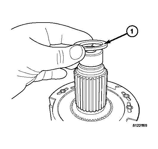
| 1 - CLUTCH SHAFT THRUST RING |
- Remove the intermediate clutch shaft thrust ring (1). See Fig 31.
 Courtesy of DAIMLERCHRYSLER CORP.
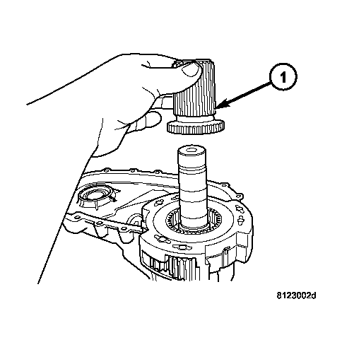
| 1 - INTERMEDIATE CLUTCH SHAFT |
- Remove the intermediate clutch shaft (1). See Fig 32.
 Courtesy of DAIMLERCHRYSLER CORP.
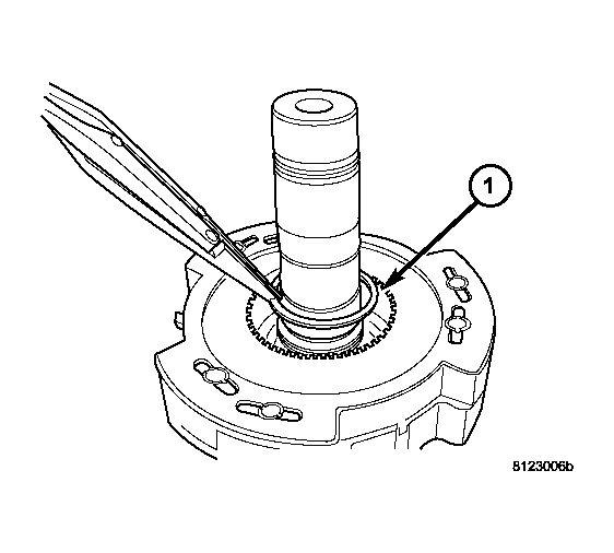
| 1 - DIFFERENTIAL SNAP-RING |
- Remove the differential snap-ring (1). See Fig 33.
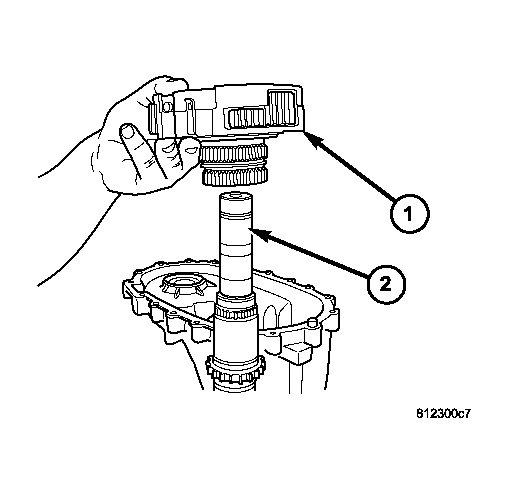 Courtesy of DAIMLERCHRYSLER CORP.
| 1 - DIFFERENTIAL ASSEMBLY |
| 2 - MAINSHAFT |
- Remove the differential assembly (1) from the mainshaft (2). See Fig 34.
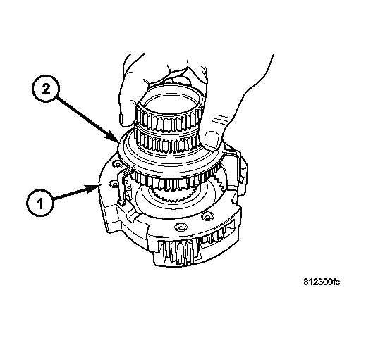 Courtesy of DAIMLERCHRYSLER CORP.
| 1 - DIFFERENTIAL ASSEMBLY |
| 2 - MODE HUB AND RETAINER |
- Remove the mode hub (2) and mode hub retainer from the differential assembly (1). See Fig 35.
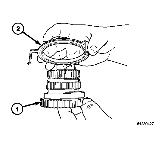 Courtesy of DAIMLERCHRYSLER CORP.
| 1 - MODE HUB RETAINER |
| 2 - MODE HUB |
- Remove the mode hub retainer (1) from the mode hub (2). See Fig 36.
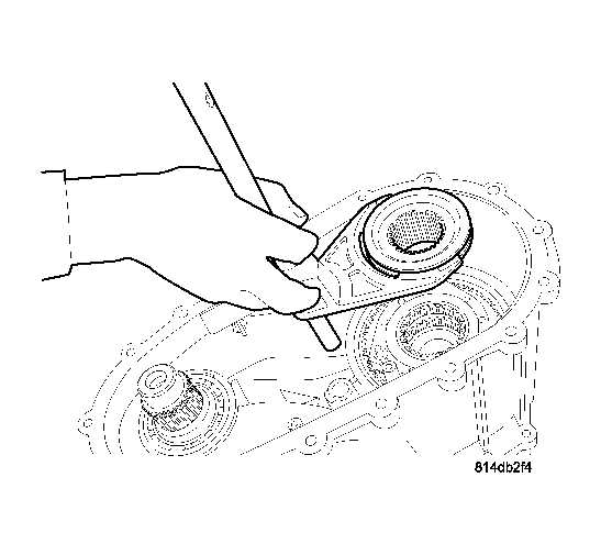 Courtesy of DAIMLERCHRYSLER CORP.
| 1 - RANGE FORK |
| 2 - RANGE HUB |
- Remove the range fork and range hub as one. See Fig 37.
 Courtesy of DAIMLERCHRYSLER CORP.
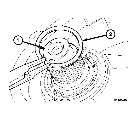
| 1 - FRONT OUTPUT SHAFT |
| 2 - RETAINING RING |
- Remove the retaining ring (2) from the front output shaft (1). See Fig 38.
 Courtesy of DAIMLERCHRYSLER CORP.
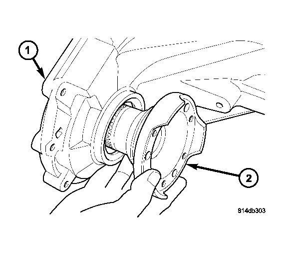
| 1 - FRONT HOUSING |
| 2 - FRONT OUTPUT SHAFT |
- Remove the front output shaft (2) from the front housing (1) and the front output shaft front bearing. See Fig 39.
 Courtesy of DAIMLERCHRYSLER CORP.
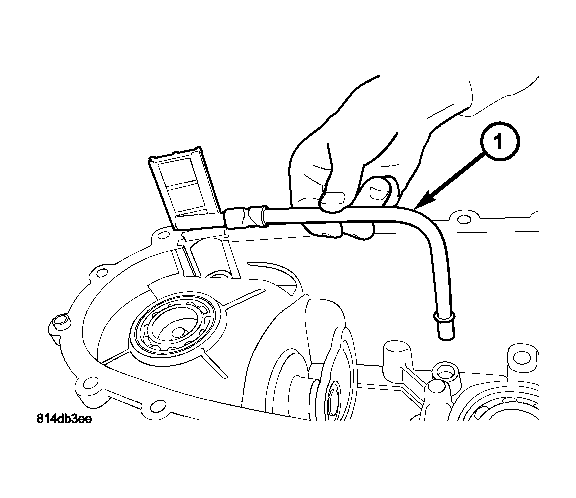
| 1 - OIL PICK-UP TUBE AND SCREEN |
- Remove the oil pick-up tube and screen (1) from the rear housing.
 Courtesy of DAIMLERCHRYSLER CORP.
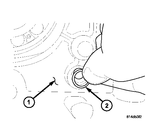
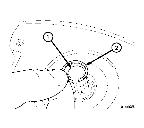
| 1 - REAR HOUSING |
| 2 - O-RING |
- Remove the oil pick-up tube o-ring (2) from the rear housing (1). See Fig 41.
 Courtesy of DAIMLERCHRYSLER CORP.
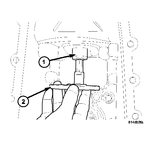
| 1 - SHIFT SECTOR |
| 2 - RETAINING RING |
- Remove the retaining ring (2) from the shift sector shaft (1). See Fig 42.
 Courtesy of DAIMLERCHRYSLER CORP.
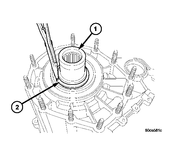
| 1 - FRONT HOUSING |
| 2 - SHIFT SECTOR |
- Remove the shift sector (2) from the rear housing (1). See Fig 43.
 Courtesy of DAIMLERCHRYSLER CORP.
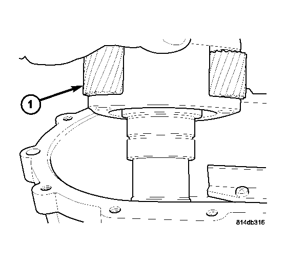
| 1 - INPUT GEAR |
| 2 - RETAINING RING |
- Remove the input shaft seal with a suitable pry tool or a screw mounted in a slide hammer.
- Remove the retaining ring (2) holding the input gear assembly into the front housing. See Fig 44.
 Courtesy of DAIMLERCHRYSLER CORP.
| 1 - INPUT GEAR AND LOW RANGE PLANETARY |
- Remove the input gear and low range planetary assembly (1) from the front housing. See Fig 45.
 Courtesy of DAIMLERCHRYSLER CORP.
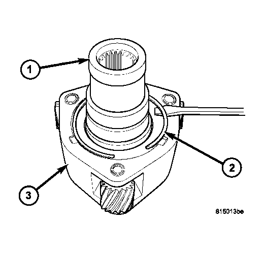
| 1 - INPUT GEAR |
| 2 - SNAP-RING |
| 3 - LOW RANGE PLANETARY |
- Remove the snap-ring (2) holding the input gear (1) into the low range planetary (3). See Fig 46.
 Courtesy of DAIMLERCHRYSLER CORP.
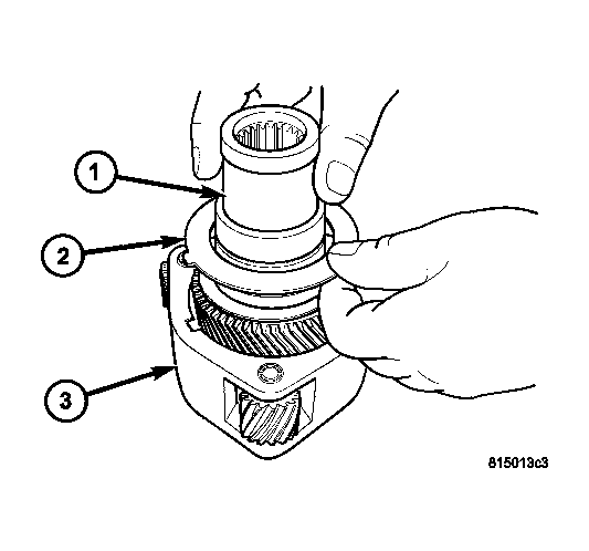
| 1 - INPUT GEAR |
| 2 - LOCK PLATE |
| 3 - LOW RANGE PLANETARY |
- Remove the input gear (1) and lock plate (2) from the low range planetary (3) and remove the lock plate. See Fig 47.
 Courtesy of DAIMLERCHRYSLER CORP.
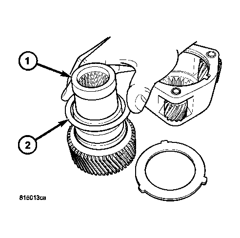
| 1 - INPUT GEAR |
| 2 - THRUST WASHER (NO TABS) |
- Remove the top thrust washer (no tabs) (2) from the input gear (1). See Fig 48.
 Courtesy of DAIMLERCHRYSLER CORP.
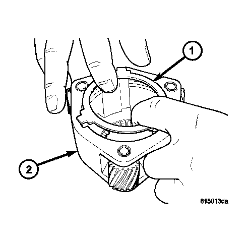
| 1 - BOTTOM THRUST WASHER (3 TABS) |
| 2 - LOW RANGE PLANETARY |
- Remove the bottom thrust washer (3 tabs) (1) from the low range planetary (2). See Fig 49.