Selector Lever Removal/Installation
- Disconnect the negative battery cable. (See NEGATIVE BATTERY CABLE DISCONNECTION/CONNECTION
).
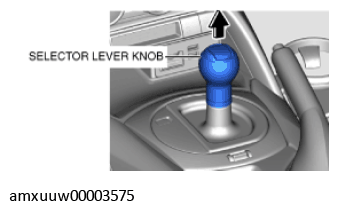
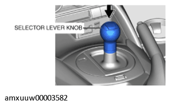
- Perform the following procedure to remove the selector lever knob.
- Shift the selector lever to the D position.
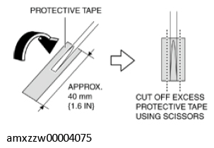
- To prevent scratches or damage, apply protective tape to the tool (width is 2 mm {0.08 in} or less, thickness is 1 mm {0.04 in} or less).
 Courtesy of MAZDA MOTORS CORP.
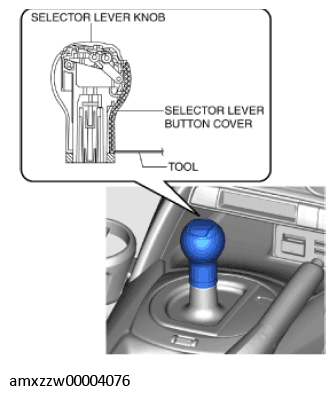
- Insert the tool as shown in the figure.
 Courtesy of MAZDA MOTORS CORP.
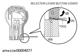
- Slowly move the tool in the direction of arrow (1) shown in the figure, detach the tab, and then remove the selector lever button cover in the direction of arrow (2).
 Courtesy of MAZDA MOTORS CORP.
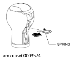
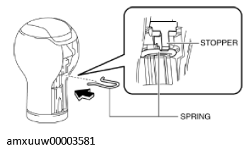
- Remove the spring.
 Courtesy of MAZDA MOTORS CORP.
- Remove the selector lever knob.
 Courtesy of MAZDA MOTORS CORP.
- Remove the following parts:
- Shift panel component (See SHIFT PANEL REMOVAL/INSTALLATION
).
- Upper panel (See UPPER PANEL REMOVAL/INSTALLATION
).
- Parking brake lever boot panel (See PARKING BRAKE LEVER BOOT PANEL REMOVAL/INSTALLATION
).
- Rear console (See REAR CONSOLE REMOVAL/INSTALLATION
).
- Front console panel (See FRONT CONSOLE PANEL REMOVAL/INSTALLATION
).
- Front console component (See FRONT CONSOLE REMOVAL/INSTALLATION
).
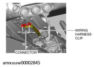
- Disconnect the connector and wiring harness clip.
 Courtesy of MAZDA MOTORS CORP.
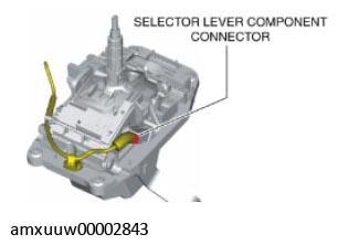
- Disconnect the selector lever component connector.
 Courtesy of MAZDA MOTORS CORP.
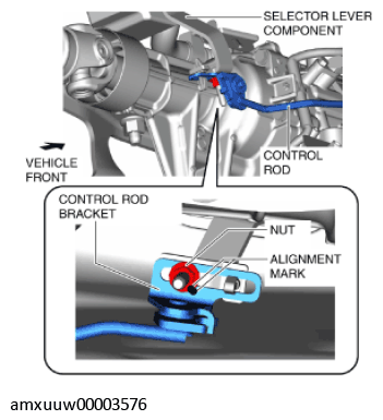
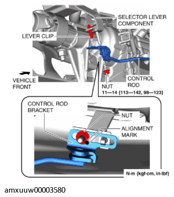
- Place alignment marks on the control rod bracket and nut.
 Courtesy of MAZDA MOTORS CORP.
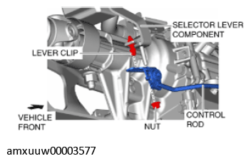
- Remove the nut.
 Courtesy of MAZDA MOTORS CORP.
- Disconnect the control rod from the lever clip of the selector lever component.
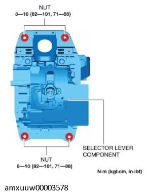
- Remove the nuts from the selector lever component.
 Courtesy of MAZDA MOTORS CORP.
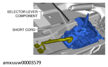
- Set the short cord aside and remove the selector lever component.
 Courtesy of MAZDA MOTORS CORP.
- Pass the short cord through the installation hole and install the selector lever component.
- Install the nuts to the selector lever component.
Courtesy of MAZDA MOTORS CORP.
- Assemble the control rod to the lever clip of the selector lever component.
 Courtesy of MAZDA MOTORS CORP.
- Align the alignment marks on the control rod bracket and nut, and install the nut.
- Connect the selector lever component connector.
Courtesy of MAZDA MOTORS CORP.
- Connect the connector and wiring harness clip.
Courtesy of MAZDA MOTORS CORP.
- Install the following parts:
- Front console component (See FRONT CONSOLE REMOVAL/INSTALLATION
).
- Front console panel (See FRONT CONSOLE PANEL REMOVAL/INSTALLATION
).
- Rear console (See REAR CONSOLE REMOVAL/INSTALLATION
).
- Parking brake lever boot panel (See PARKING BRAKE LEVER BOOT PANEL REMOVAL/INSTALLATION
).
- Upper panel (See UPPER PANEL REMOVAL/INSTALLATION
).
- Shift panel component (See SHIFT PANEL REMOVAL/INSTALLATION
).
- Perform the following procedure to install the selector lever knob.
- Install the spring to the selector lever knob.
 Courtesy of MAZDA MOTORS CORP.
CAUTION:
- Install the spring so that it is stopped by the stopper.
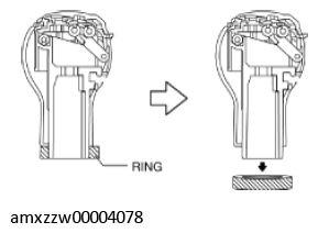
- Remove the ring shown in the figure.
 Courtesy of MAZDA MOTORS CORP.
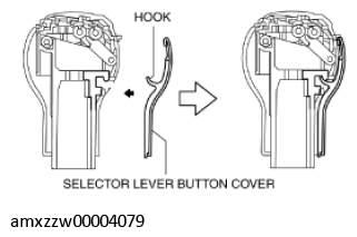
- Attach the selector lever button cover hook to the position shown in the figure and install the selector lever button cover.
 Courtesy of MAZDA MOTORS CORP.
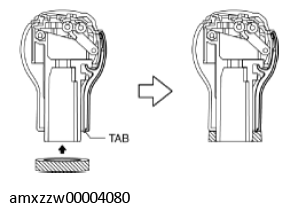
- Insert the tab of the selector lever button cover lower end into the groove of the ring, and install the ring.
 Courtesy of MAZDA MOTORS CORP.
- Install the selector lever knob to the selector lever component.
 Courtesy of MAZDA MOTORS CORP.
- Pull the select lever knob upward and verify that it is securely installed.
- Connect the negative battery cable. (See NEGATIVE BATTERY CABLE DISCONNECTION/CONNECTION
).