- Turn ignition on, with engine off. If other warning lights illuminate, go to next step. If no lights illuminate, repair instrument cluster.
- Turn ignition off. Remove instrument cluster. Check ABS warning light bulb. If bulb is okay, go to next step. If bulb is bad, replace bulb and retest.
- Disconnect bulkhead connector B100 from bulkhead connector F2, located at top left corner of dash. On Forester models, connector is Black. On all other models, connector is Blue. Measure voltage between ground and appropriate terminal at connector B100. See CONNECTOR B100 TERMINAL IDENTIFICATION
table. For terminal locations, see Fig 1
-8.
- On all models, if voltage is less than 3 volts, go to next step. If voltage is more than 3 volts, repair ABS warning light wiring harness between bulkhead connector B100 and instrument cluster.
CONNECTOR B100 TERMINAL IDENTIFICATION
| Model |
No. Of Pins |
Terminal No. |
| Forester |
24 |
15 |
| Impreza |
16 |
8 |
| Legacy |
20 |
9 |
- Turn ignition on. Measure voltage between ground and appropriate terminal at bulkhead connector B100. See CONNECTOR B100 TERMINAL IDENTIFICATION
table. For terminal locations, see Fig 1
-8. If voltage is less than 3 volts, go to next step. If voltage is more than 3 volts, repair ABS warning light wiring harness between bulkhead connector B100 and instrument cluster.
- Turn ignition off. Ensure ABS warning light bulb is installed in instrument cluster. Install instrument cluster. Turn ignition on. Measure voltage between ground and appropriate terminal at connector B100. See CONNECTOR B100 TERMINAL IDENTIFICATION
table. For terminal locations, see Fig 1
-8. If voltage is 10-15 volts, go to ne xt step. If voltage is not 10-15 volts, repair wiring harness between bulkhead connector B100 and instrument cluster.
- Turn ignition off. Measure voltage between ground and appropriate terminal at bulkhead connector F2. Bulkhead connector F2 is a mirror image of bulkhead connector B100. See CONNECTOR F2 TERMINAL IDENTIFICATION table. If voltage is less than 3 volts, go to next step. If voltage is more than 3 volts, repair wiring harness between ABSCM/HU and instrument cluster.
CONNECTOR F2 TERMINAL IDENTIFICATION
| Model |
No. Of Pins |
Terminal No. |
| Forester |
24 |
15 |
| Impreza |
16 |
8 |
| Legacy |
20 |
9 |
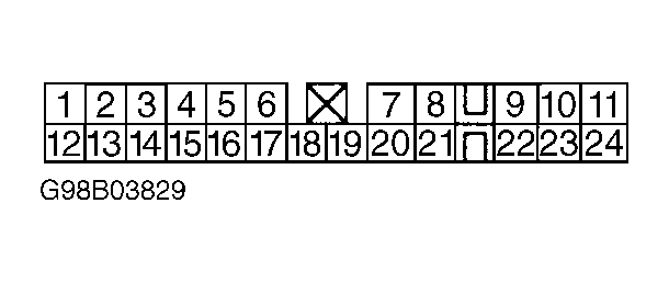 Courtesy of SUBARU OF AMERICA, INC.
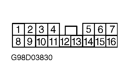 Courtesy of SUBARU OF AMERICA, INC.
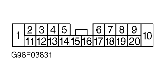 Courtesy of SUBARU OF AMERICA, INC.
- Turn ignition on. Measure voltage between ground and appropriate terminal at bulkhead connector F2. See CONNECTOR F2 TERMINAL IDENTIFICATION table. If voltage is less than 3 volts, go to next step. If voltage is more than 3 volts, repair wiring harness between ABSCM/HU and instrument cluster.
- Measure resistance between ground and terminal No. 23 at ABSCM/HU connector. See Figure
. If resistance is less than .5 ohm, go to next step. If resistance is more than .5 ohm, repair wiring harness between ground and ABSCM/HU.
- Measure resistance between ground and appropriate terminal at bulkhead connector F2. See CONNECTOR F2 TERMINAL IDENTIFICATION table. If resistance is less than .5 ohm, go to next step. If resistance is more than .5 ohm, repair wiring harness or bulkhead connector F2.
- Turn ignition off. Check connectors at instrument cluster and ABSCM/HU. If connector contacts are poor, repair connector as necessary. If contacts are okay, replace ABSCM/HU.