Assembly (1)
- Install manual shaft components.
- Install oil seal onto manual shaft.
- Apply ATF to oil seal.
- Wrap threads of manual shaft with masking tape.
- Insert manual shaft and oil seal as a unit into transmission case.
- Remove masking tape.
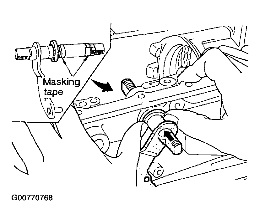 Courtesy of NISSAN MOTOR CO., U.S.A.
- Push oil seal evenly and install it onto transmission case.
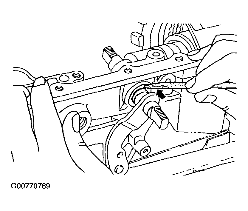 Courtesy of NISSAN MOTOR CO., U.S.A.
- Align groove in shaft with drive pin hole; then drive pin into position as shown in Fig 3.
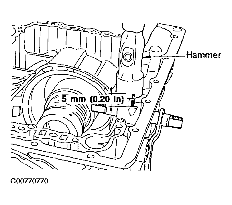 Courtesy of NISSAN MOTOR CO., U.S.A.
- Install detent spring and spacer.
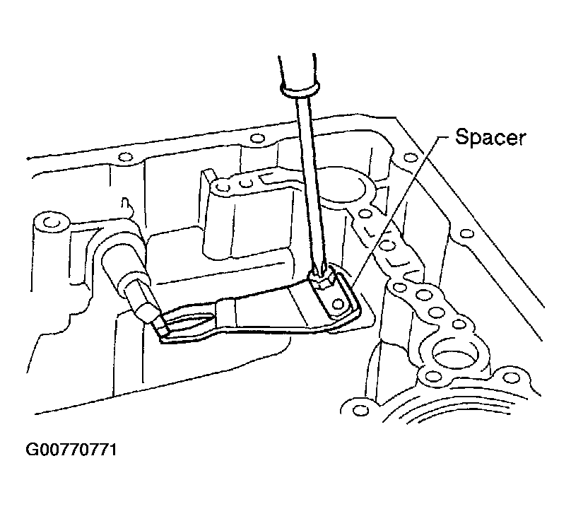 Courtesy of NISSAN MOTOR CO., U.S.A.
- While pushing detent spring down, install manual plate onto manual shaft.
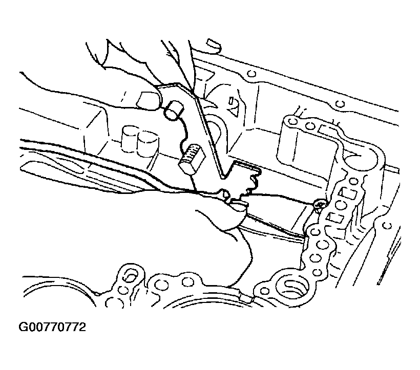 Courtesy of NISSAN MOTOR CO., U.S.A.
- Install lock nuts onto manual shaft.
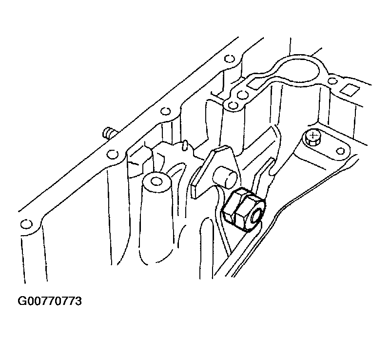 Courtesy of NISSAN MOTOR CO., U.S.A.
- Install throttle lever components.
- Install throttle lever shaft.
- Align groove in shaft with drive pin hole, then drive pin into position as shown in Fig 7.
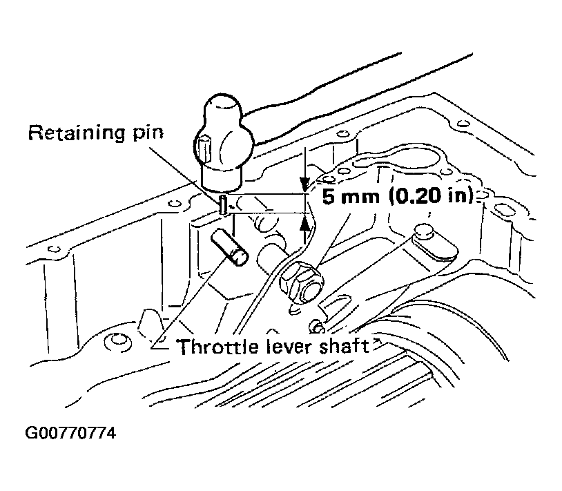 Courtesy of NISSAN MOTOR CO., U.S.A.
- Install throttle lever, return spring, spring retainer and E-ring.
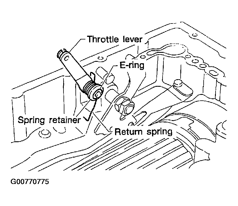 Courtesy of NISSAN MOTOR CO., U.S.A.
- Install throttle wire.
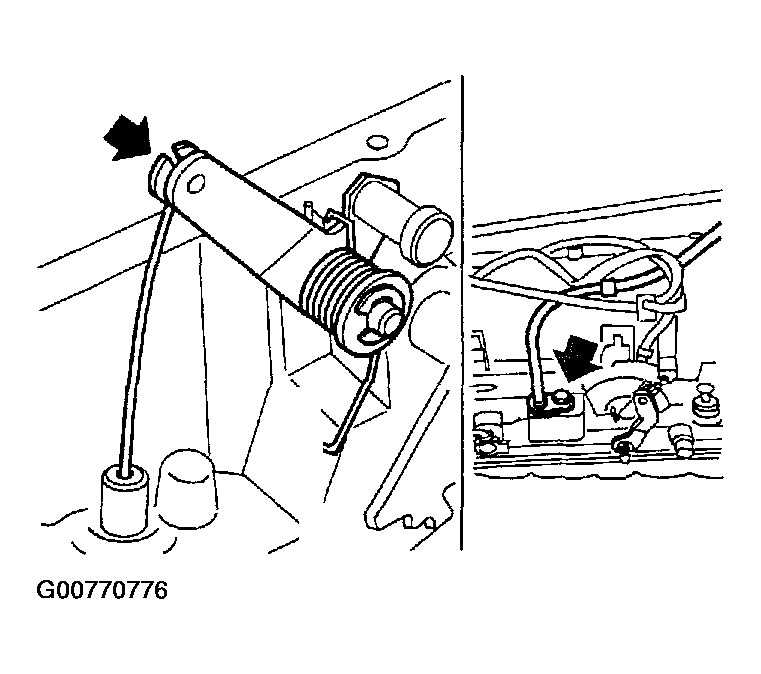 Courtesy of NISSAN MOTOR CO., U.S.A.
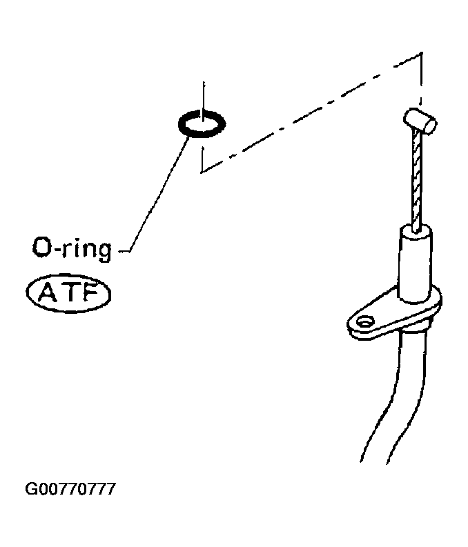 Courtesy of NISSAN MOTOR CO., U.S.A.
- Install accumulator piston.
- Install O-rings onto accumulator piston.
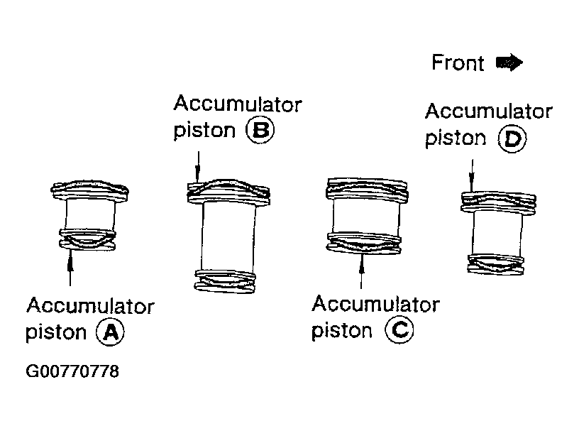 Courtesy of NISSAN MOTOR CO., U.S.A.
- Install return spring for accumulator A onto transmission case.
- Free length of return spring :
Refer to
RETURN SPRINGS .
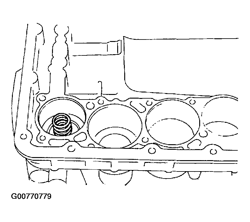 Courtesy of NISSAN MOTOR CO., U.S.A.
- Install accumulator pistons A, B, C
and D
.
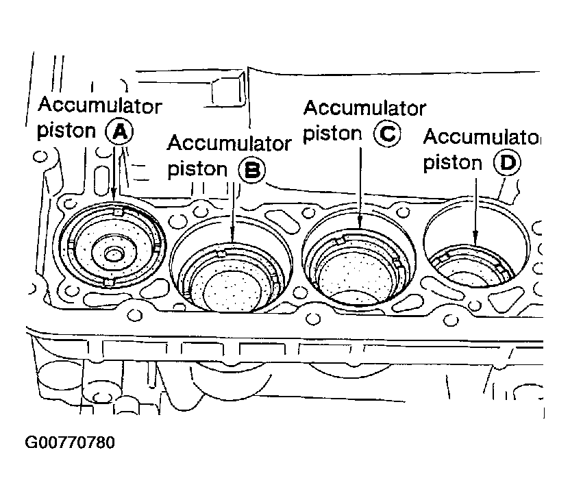 Courtesy of NISSAN MOTOR CO., U.S.A.
- Apply ATF to transmission case.
- Install band servo piston.
- Install return springs onto band servo piston.
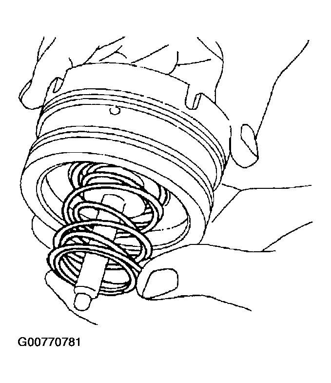 Courtesy of NISSAN MOTOR CO., U.S.A.
- Install band servo piston onto transmission case.
- Apply ATF to O-ring of band servo piston and transmission case.
- Install gasket for band servo onto transmission case.
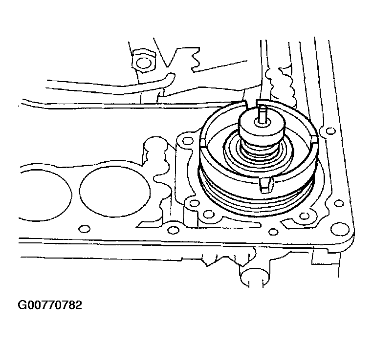 Courtesy of NISSAN MOTOR CO., U.S.A.
- Install O/D servo piston retainer onto transmission case.
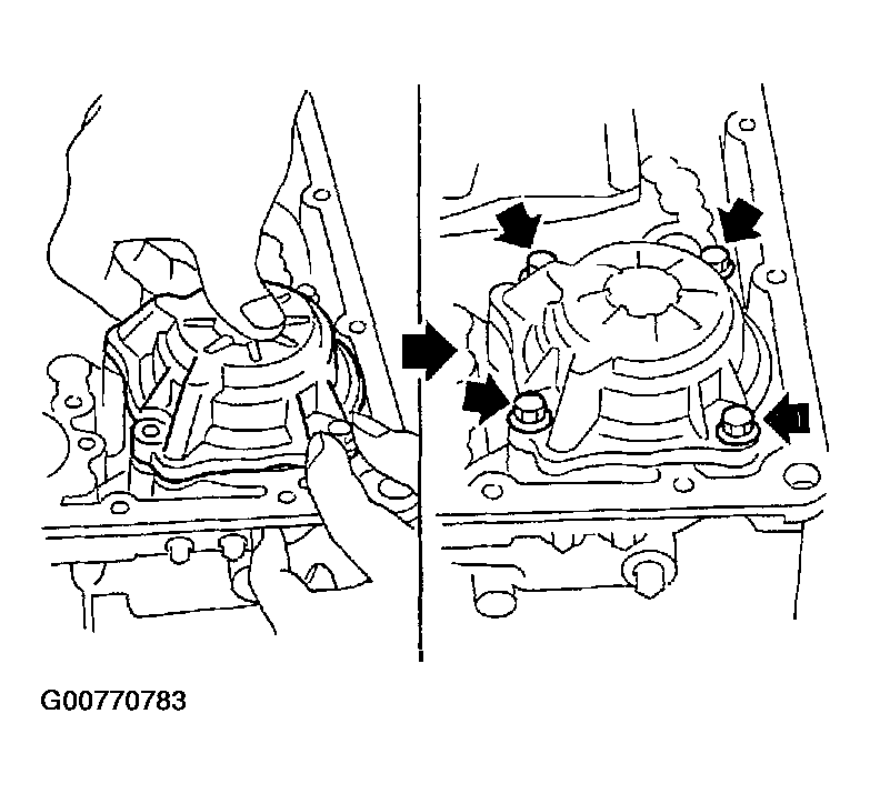 Courtesy of NISSAN MOTOR CO., U.S.A.
- Install rear side clutch and gear components.
- Place transmission case in vertical position.
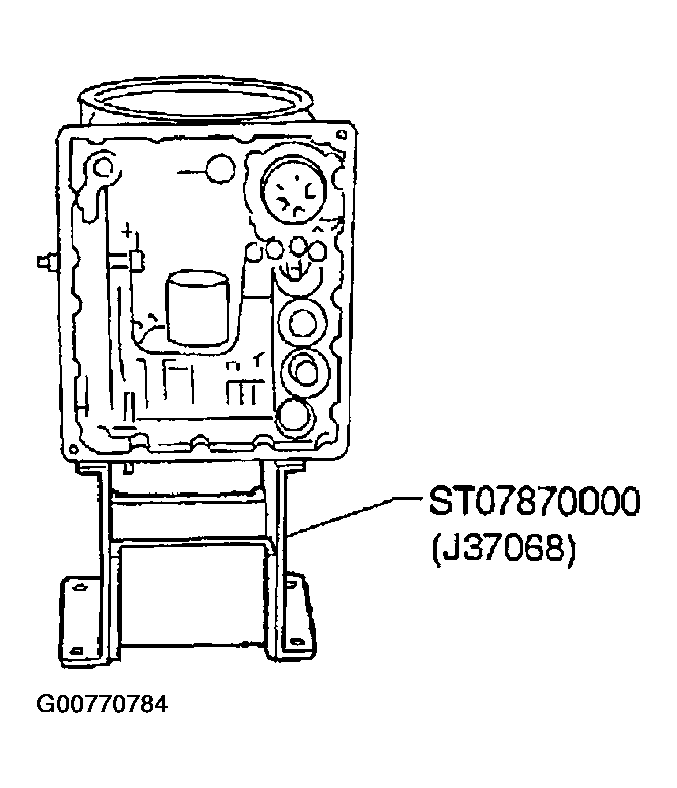 Courtesy of NISSAN MOTOR CO., U.S.A.
- Slightly lift forward clutch drum assembly and slowly rotate it clockwise until its hub passes fully over the clutch inner race inside transmission case.
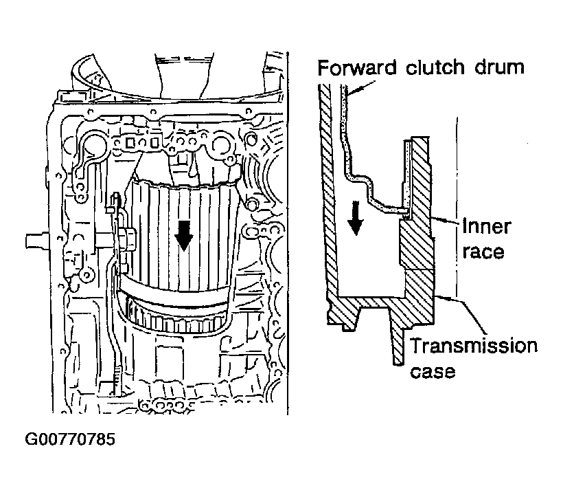 Courtesy of NISSAN MOTOR CO., U.S.A.
- Check to be sure that rotation direction of forward clutch assembly is correct.
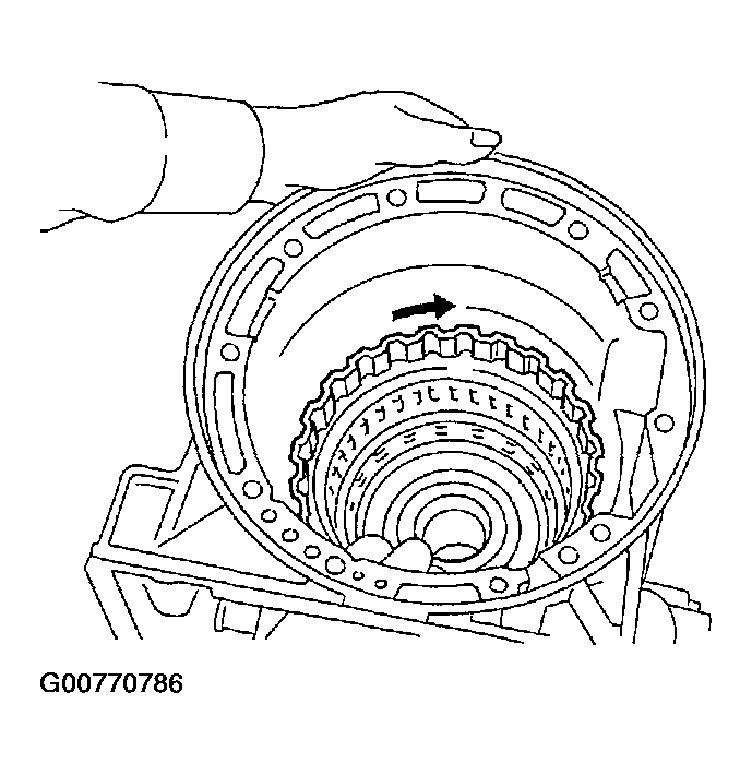 Courtesy of NISSAN MOTOR CO., U.S.A.
- Install thrust washer onto front of overrun clutch hub.
- Apply petroleum jelly to the thrust washer.
- Insert pawls of thrust washer securely into holes in overrun clutch hub.
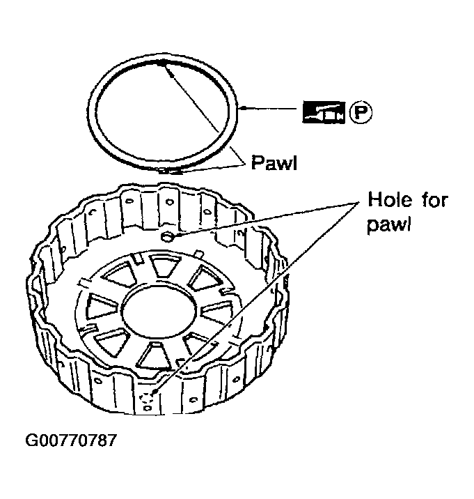 Courtesy of NISSAN MOTOR CO., U.S.A.
- Install overrun clutch hub onto rear internal gear assembly.
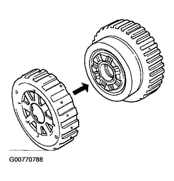 Courtesy of NISSAN MOTOR CO., U.S.A.
- Install needle bearing onto rear of overrun clutch hub.
- Apply petroleum jelly to needle bearing.
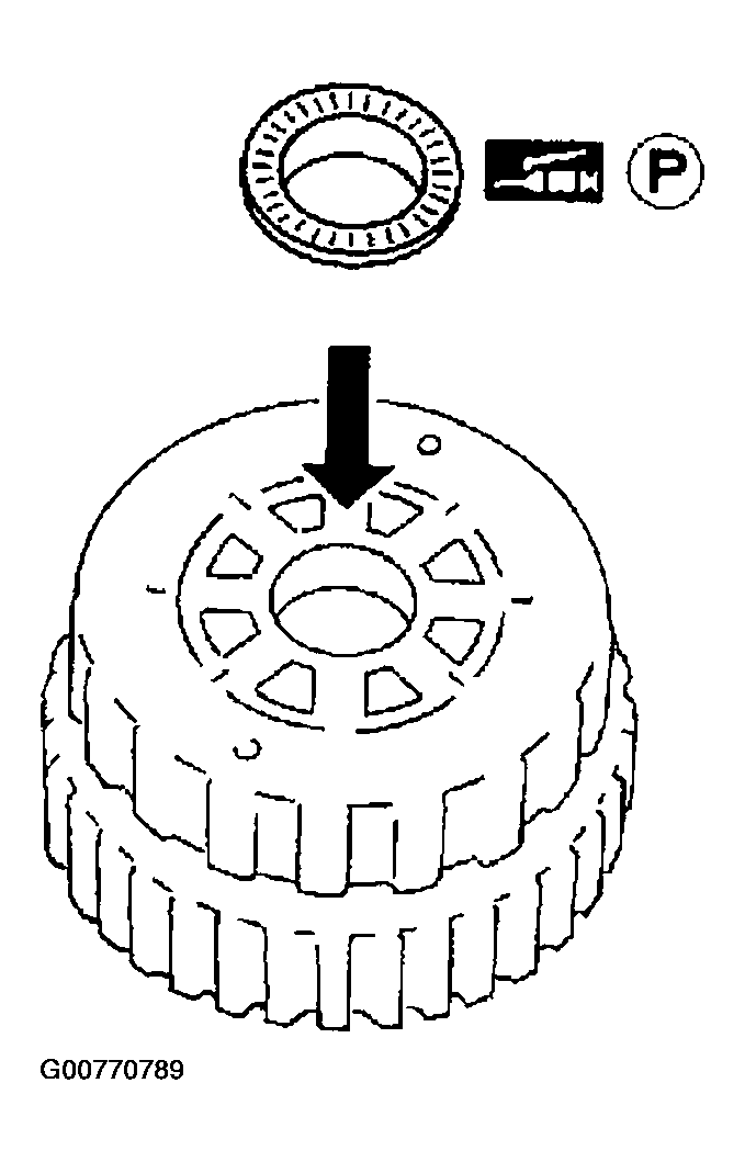 Courtesy of NISSAN MOTOR CO., U.S.A.
- Check that overrun clutch hub rotates as shown in Fig 23 while holding forward clutch hub.
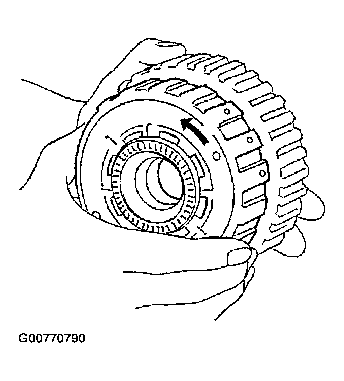 Courtesy of NISSAN MOTOR CO., U.S.A.
- Place transmission case into horizontal position.
- Install rear internal gear, forward clutch hub and overrun clutch hub as a unit onto transmission case.
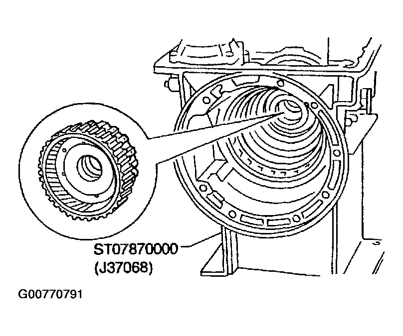 Courtesy of NISSAN MOTOR CO., U.S.A.
- Install needle bearing onto rear internal gear.
- Apply petroleum jelly to needle bearing.
- Install bearing race onto rear of front internal gear.
- Apply petroleum jelly to bearing race.
- Securely engage pawls of bearing race with holes in front internal gear.
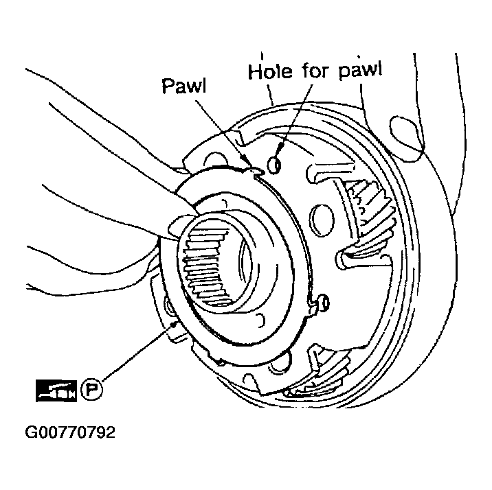 Courtesy of NISSAN MOTOR CO., U.S.A.
- Install front internal gear on transmission case.
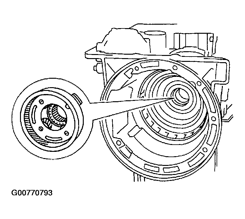 Courtesy of NISSAN MOTOR CO., U.S.A.
- Install output shaft and parking gear.
- Insert output shaft from rear of transmission case while slightly lifting front internal gear.
- Do not force output shaft against front of transmission case.
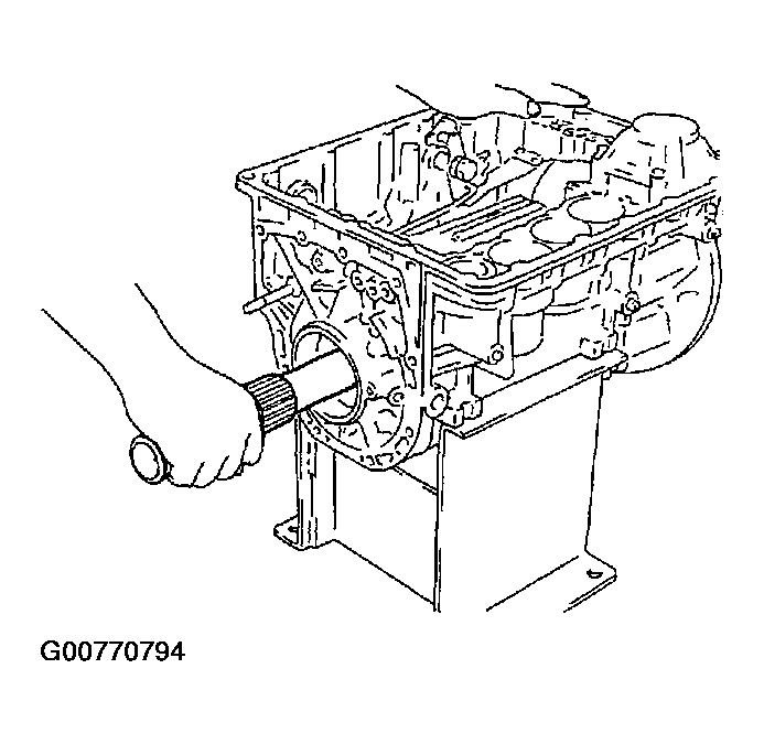 Courtesy of NISSAN MOTOR CO., U.S.A.
- Carefully push output shaft against front of transmission case. Install snap ring on front of output shaft.
- Check to be sure output shaft cannot be removed in rear direction.
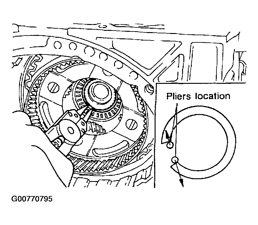 Courtesy of NISSAN MOTOR CO., U.S.A.
- Install needle bearing on transmission case.
- Pay attention to its direction - black side faces the rear.
- Apply petroleum jelly to needle bearing.
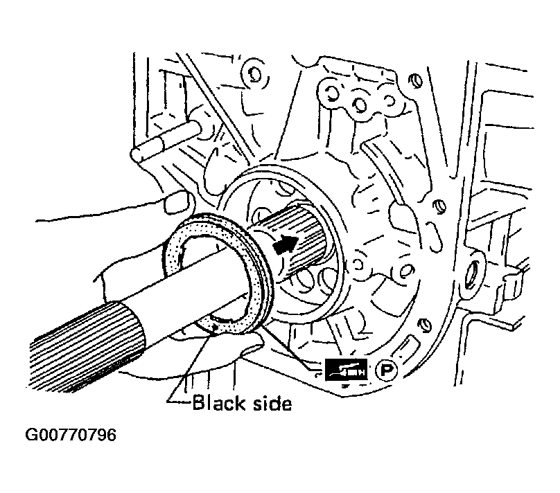 Courtesy of NISSAN MOTOR CO., U.S.A.
- Install parking gear on transmission case.
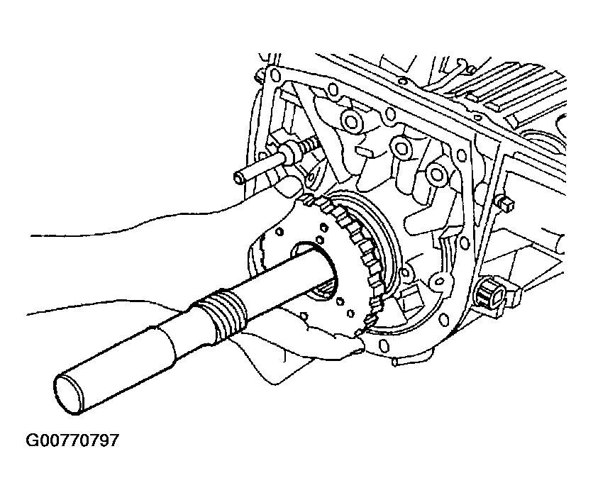 Courtesy of NISSAN MOTOR CO., U.S.A.
- Install snap ring on rear of output shaft.
- Check to be sure output shaft cannot be removed in forward direction.
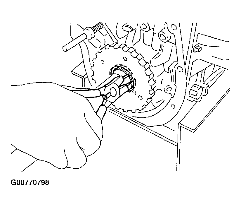 Courtesy of NISSAN MOTOR CO., U.S.A.
- Install governor valve assembly on oil distributor.
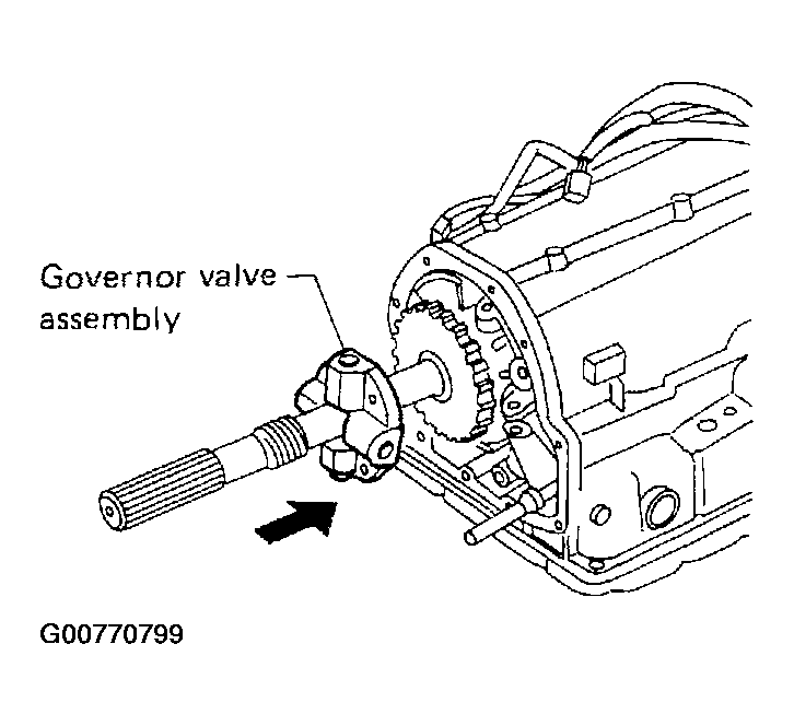 Courtesy of NISSAN MOTOR CO., U.S.A.
- Install rear extension case.
- Install oil seal on rear extension case.
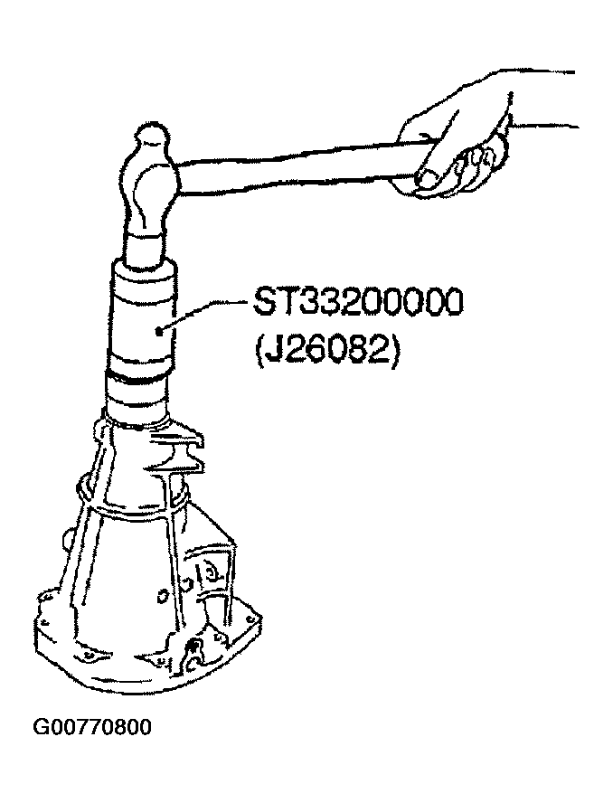 Courtesy of NISSAN MOTOR CO., U.S.A.
- Install rear extension gasket on transmission case.
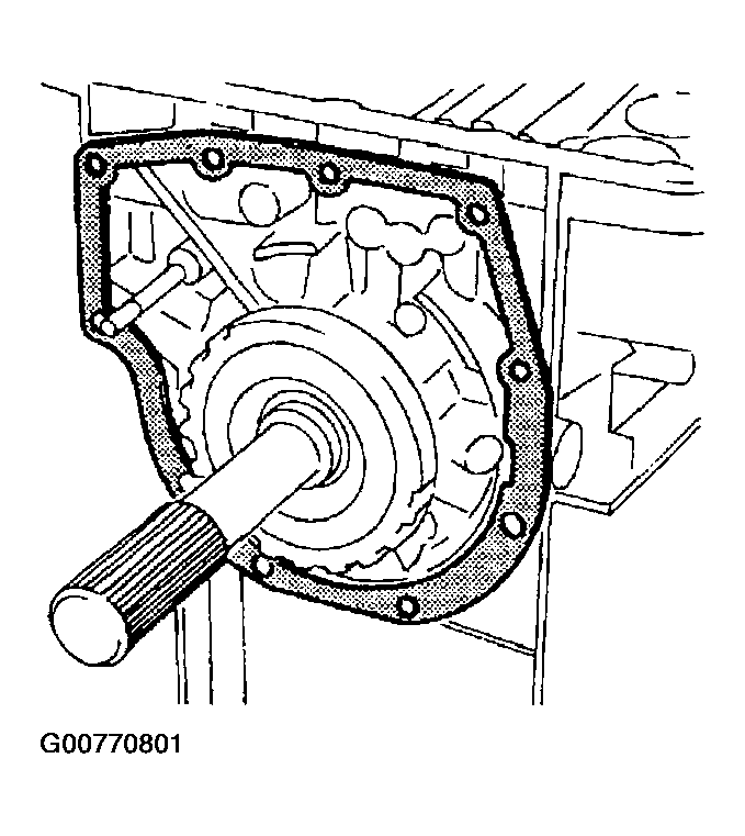 Courtesy of NISSAN MOTOR CO., U.S.A.
- Install parking rod on transmission case.
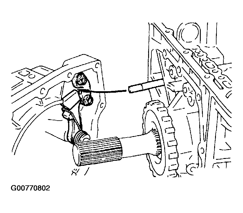 Courtesy of NISSAN MOTOR CO., U.S.A.
- Install rear extension case on transmission case. Tighten bolts to specified torque.
- : 20 - 25 N.m (2.0 - 2.5 kg-m, 14 - 18 ft-lb)
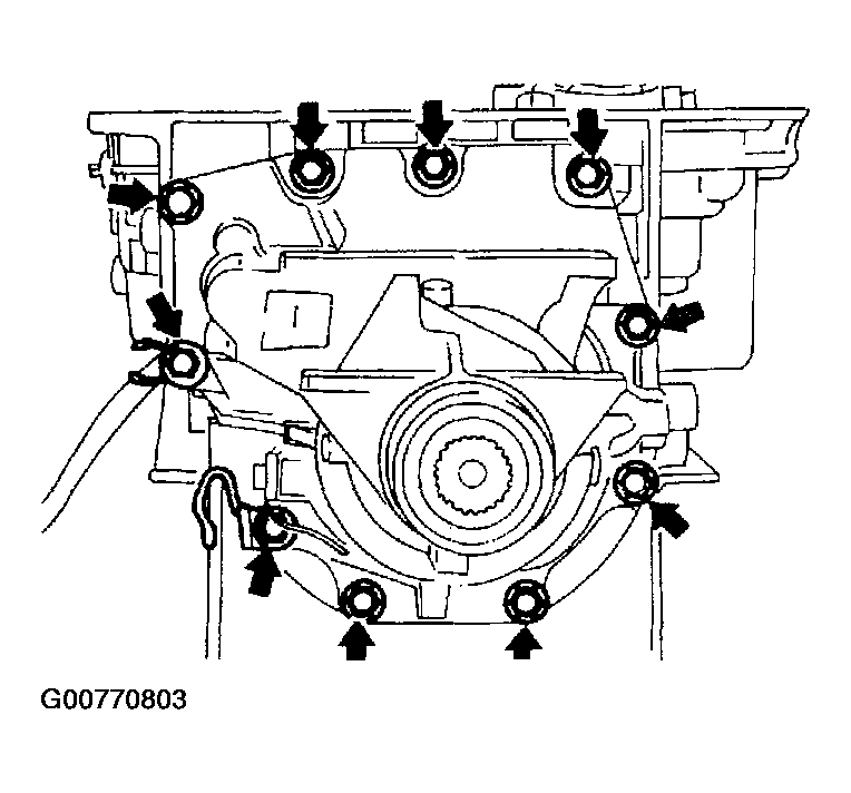 Courtesy of NISSAN MOTOR CO., U.S.A.
- Install front side clutch and gear components.
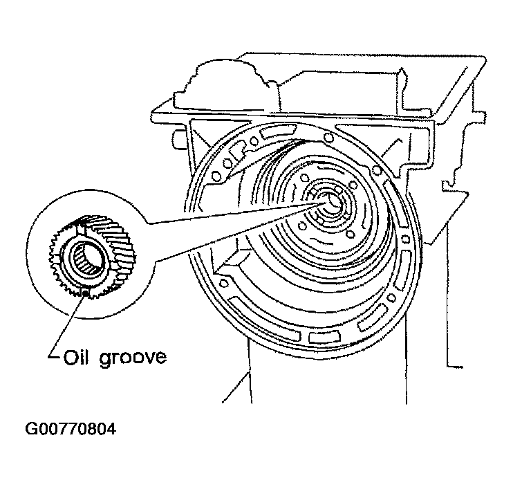
- Install rear sun gear on transmission case.
- Pay attention to its direction.
 Courtesy of NISSAN MOTOR CO., U.S.A.
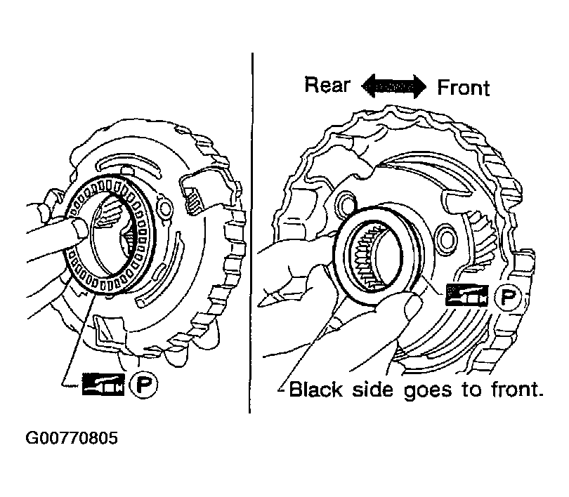
- Install needle bearing on front of front planetary carrier.
- Apply petroleum jelly to needle bearing.
- Install needle bearing on rear of front planetary carrier.
- Apply petroleum jelly to needle bearing.
- Pay attention to its direction - black side faces the front.
 Courtesy of NISSAN MOTOR CO., U.S.A.
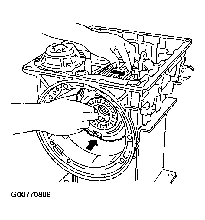
- While rotating forward clutch drum clockwise, install front planetary carrier on forward clutch drum.
 Courtesy of NISSAN MOTOR CO., U.S.A.
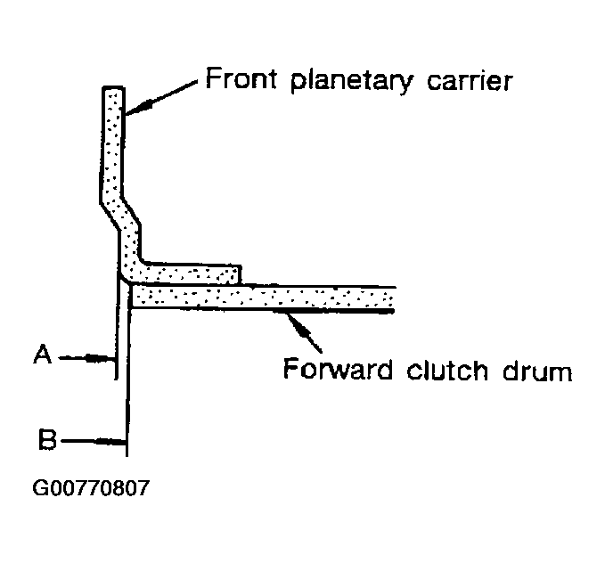
- Check that portion A of front planetary carrier protrudes approximately 2 mm (0.08 in) beyond portion B of forward clutch assembly.
 Courtesy of NISSAN MOTOR CO., U.S.A.
- Install bearing races on front and rear of clutch pack.
- Apply petroleum jelly to bearing races.
- Securely engage pawls of bearing races with holes in clutch pack.
- Place transmission case in vertical position.
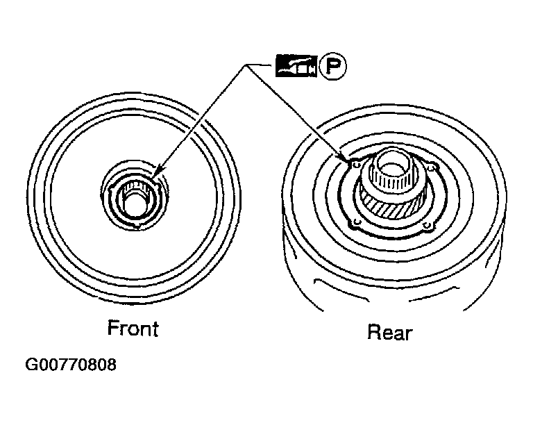 Courtesy of NISSAN MOTOR CO., U.S.A.
- Install clutch pack into transmission case.
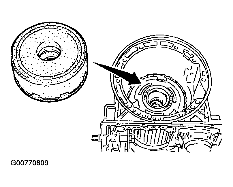 Courtesy of NISSAN MOTOR CO., U.S.A.