Dashboard Installation
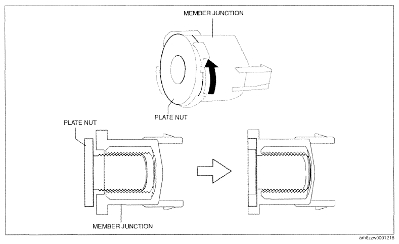
- Rotate the plate nuts by hand in the direction of the arrow shown in the figure until they are seated.
CAUTION:
- After removing the dashboard, the plate nuts of the member junctions will have lifted. If the dashboard is removed with the plate nuts lifted, the plate nuts may contact the vehicle body, causing a dent or damage to the coating film, and the dashboard installation will be difficult. Before inserting the dashboard into the cabin, adjust the plate nuts of the member junctions.
- If the plate nuts are tightened completely when installing bolts, the plate nuts may not move resulting in damage to the member junction tab and the vehicle body. After seating the plate nuts, verify that they can be rotated by hand.
NOTE:
- If the plate nuts cannot be rotated by hand, loosen the plate nuts using a hexagonal wrench.
 Courtesy of MAZDA MOTORS CORP.
- Insert the dashboard from the front driver-side door or front passenger-side door opening.
CAUTION:
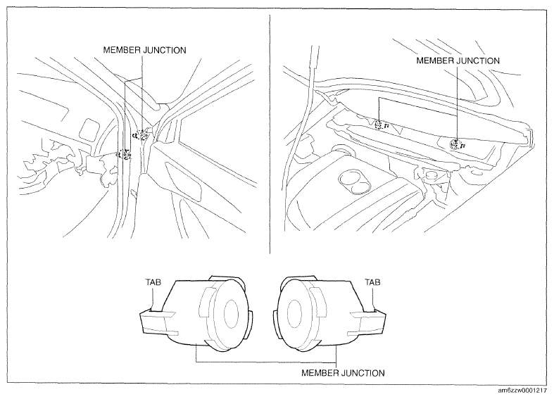
- If the member junction tabs become disengaged from the dashboard when inserting the dashboard into the cabin, the member junction could be damaged. Before inserting the dashboard, into the cabin, verify that the member junction tabs are engaged with the dashboard.
 Courtesy of MAZDA MOTORS CORP.
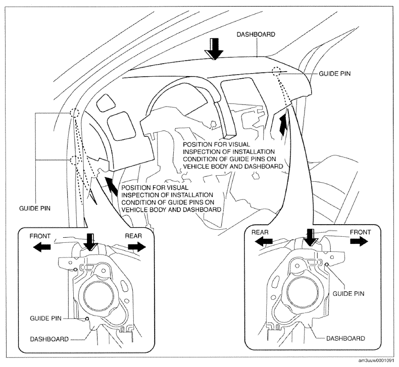
- Move the dashboard in the direction of the arrow shown in the figure, align it with the guide pins on the vehicle body sides, and set it.
 Courtesy of MAZDA MOTORS CORP.
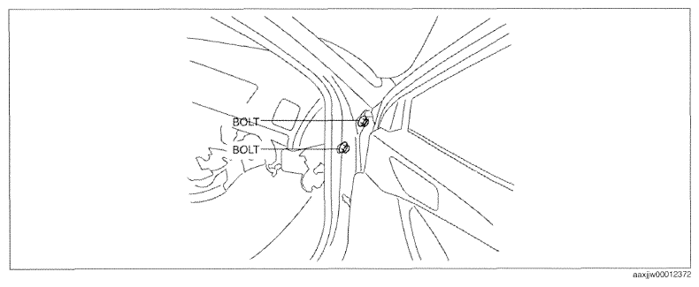
- Insert bolts on the passenger-side.
NOTE:
- Tighten bolts to the specified toque after the member junction position of bolts is positioned.
 Courtesy of MAZDA MOTORS CORP.
- Tighten bolts on the driver-side until they are seated.
NOTE:
- Do not use a tool to tighten bolts, and instead hand tighten them until they feel sufficiently tight.
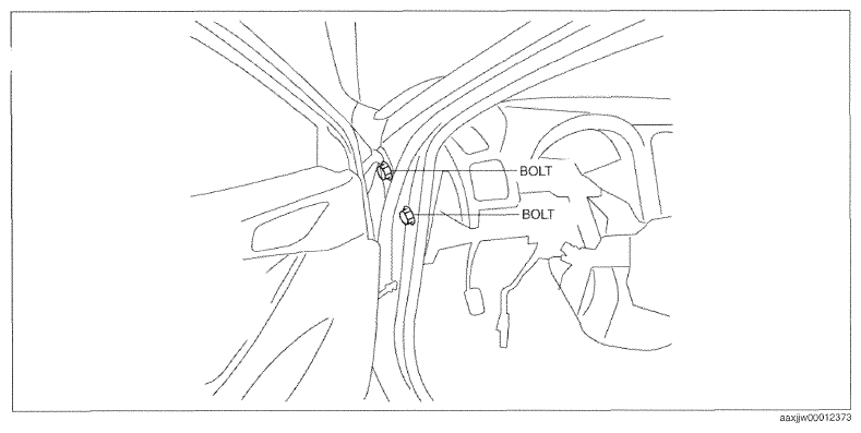 Courtesy of MAZDA MOTORS CORP.
- Tighten bolts on the passenger-side until they are seated.
NOTE:
- After bolts are seated, rotate the plate nuts of the member junctions and visually inspect them from the lower side of the dashboard on the passenger-side to verify that they emerge in the direction of the body panels.
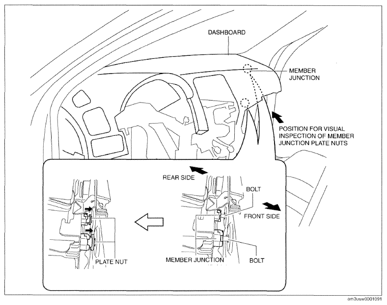 Courtesy of MAZDA MOTORS CORP.
- Verify that the member junction hole of bolt and the through-hole of bolt on the vehicle side are aligned.
NOTE:
- If the member junction hole of bolt is not aligned with the through-hole of bolt on the vehicle side, remove bolts on the driver-side and the front passenger-side, then resume the procedure from Step 5.
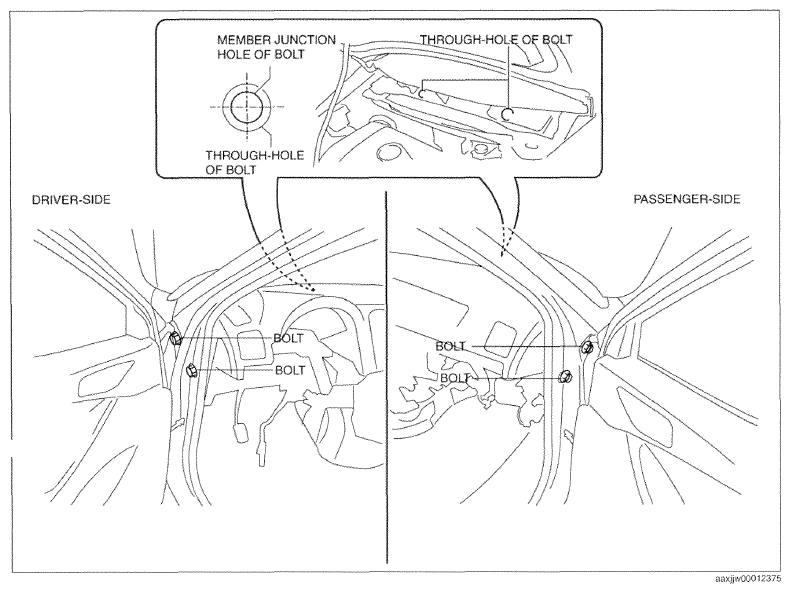 Courtesy of MAZDA MOTORS CORP.
- Seated bolts.
CAUTION:
- If bolts are reused, the plate nuts of the member junctions may not move causing damage to the member junction tabs and the vehicle body. Always replace bolts with new ones.
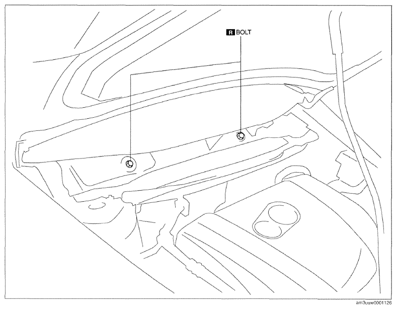 Courtesy of MAZDA MOTORS CORP.
- Completely tighten bolts on the driver-side and passenger-side to the specified torque.
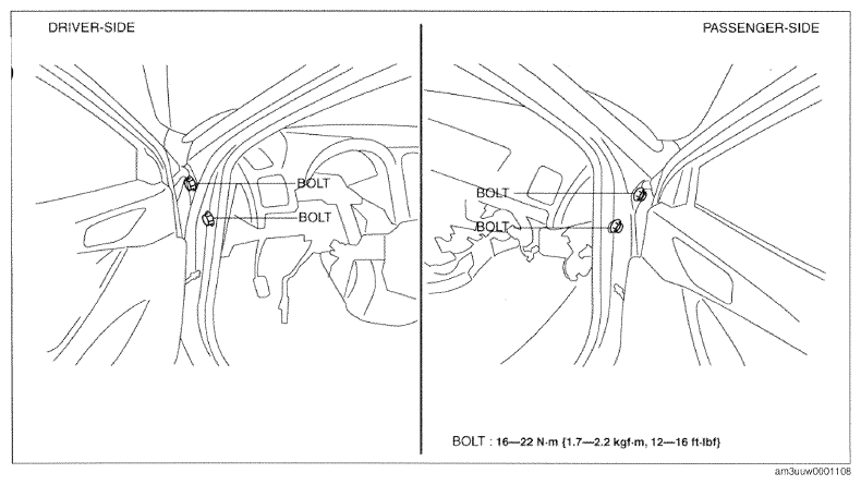 Courtesy of MAZDA MOTORS CORP.
- Completely tighten bolts to the specified torque.
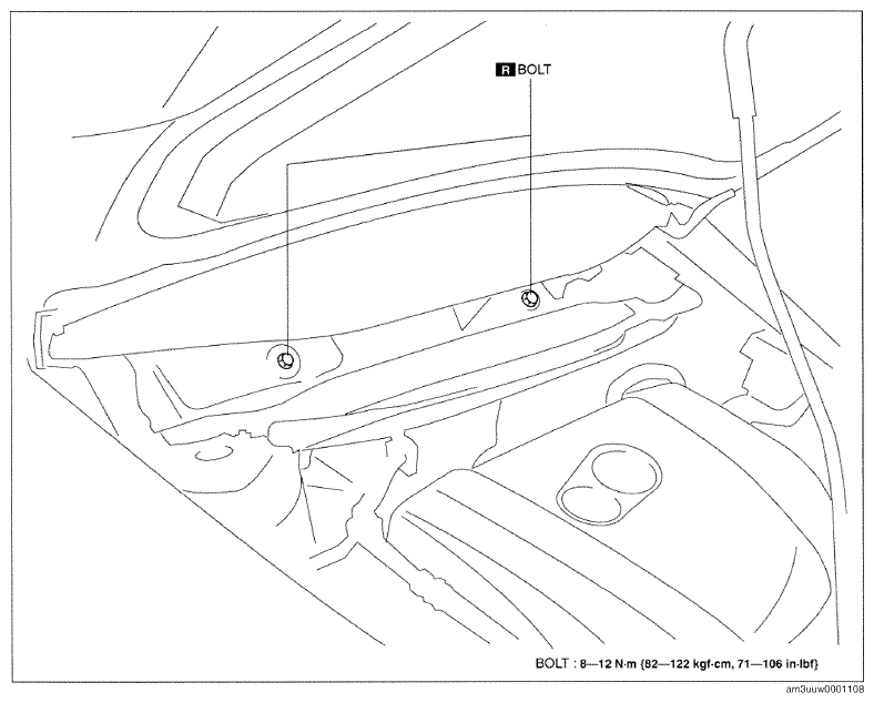 Courtesy of MAZDA MOTORS CORP.
- Install the caps.
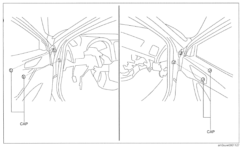 Courtesy of MAZDA MOTORS CORP.
- Install the dashboard bracket.
- Install nuts.
- Install bolts.
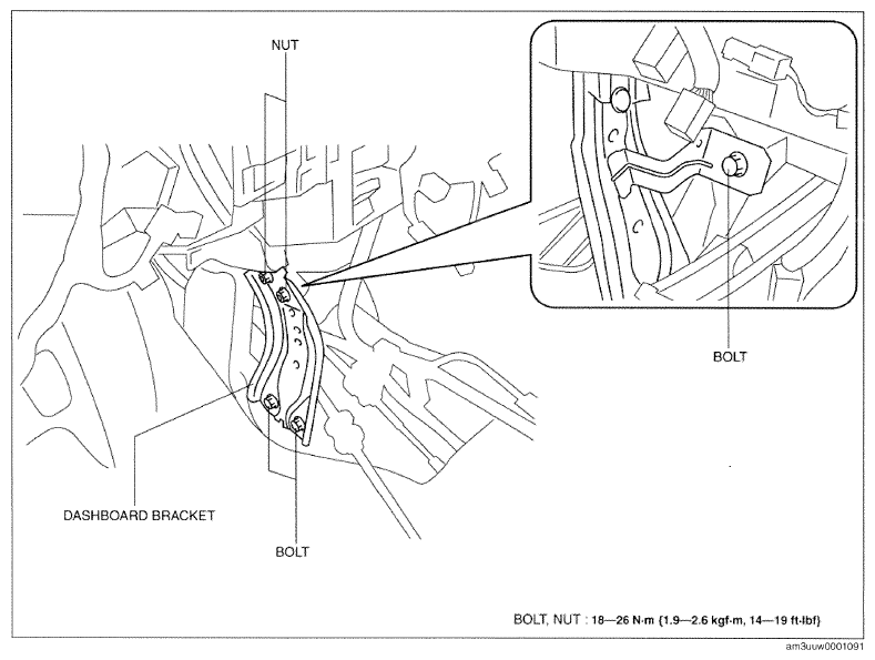 Courtesy of MAZDA MOTORS CORP.
- Install nuts.
- Install the rear console bracket.
- Connect the dashboard harness connectors and install the wiring harness clip.
- Install the parking brake lever component.
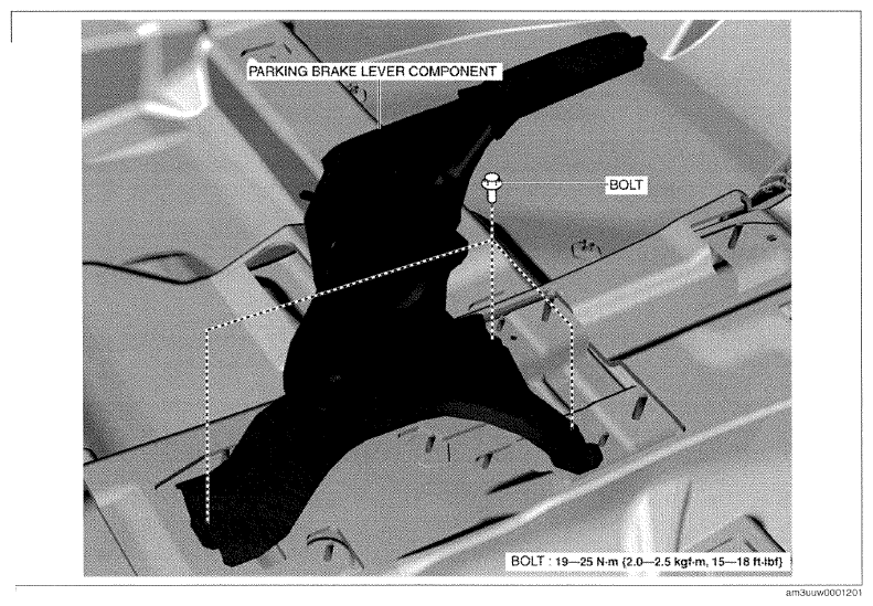 Courtesy of MAZDA MOTORS CORP.
- Install the front console bracket.
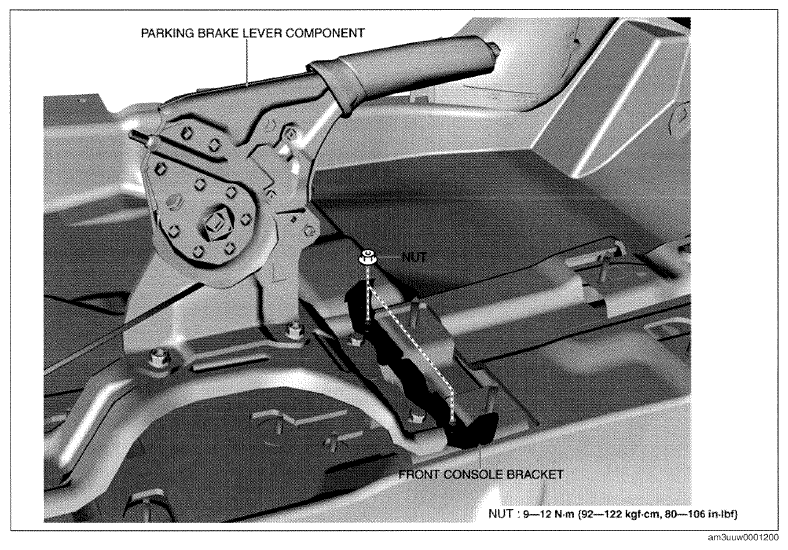 Courtesy of MAZDA MOTORS CORP.
- Install nuts.
- Install the following parts:
- Selector lever component (ATX) (See
AUTOMATIC TRANSAXLE SHIFT MECHANISM REMOVAL/INSTALLATION
.)
- Shift lever component (MTX) (See
MANUAL TRANSAXLE SHIFT MECHANISM REMOVAL/INSTALLATION [C66M-R]
.)
- Steering shaft (See
STEERING WHEEL AND COLUMN REMOVAL/INSTALLATION
.)
- Joint cover (See
STEERING WHEEL AND COLUMN REMOVAL/INSTALLATION
.)
- Knee bolster (See
KNEE BOLSTER REMOVAL/INSTALLATION .)
- Driver-side lower panel (See
LOWER PANEL REMOVAL/INSTALLATION .)
- Fuel-filler lid opener lever (See
FUEL-FILLER LID OPENER AND LEVER REMOVAL/INSTALLATION
.)
- Hood release lever (See
HOOD RELEASE LEVER AND RELEASE CABLE REMOVAL/INSTALLATION
.)
- Audio unit (without center display) (See
AUDIO UNIT REMOVAL/INSTALLATION
.)
- Center display (with center display) (See
CENTER DISPLAY REMOVAL/INSTALLATION
.)
- Climate control unit (See
CLIMATE CONTROL UNIT REMOVAL/INSTALLATION [FULL-AUTO AIR CONDITIONER]
.) (See
CLIMATE CONTROL UNIT REMOVAL/INSTALLATION [MANUAL AIR CONDITIONER]
.)
- Front console (See
FRONT CONSOLE REMOVAL/INSTALLATION .)
- Passenger-side lower panel (See
LOWER PANEL REMOVAL/INSTALLATION .)
- Decoration panel (See
DECORATION PANEL REMOVAL/INSTALLATION .)
- Dashboard undercover (See
DASHBOARD UNDER COVER REMOVAL/INSTALLATION .)
- Glove compartment (See
GLOVE COMPARTMENT REMOVAL/INSTALLATION .)
- Side wall (See
SIDE WALL REMOVAL/INSTALLATION .)
- CD player (with CD player) (See
CD PLAYER REMOVAL
.) (See
CD PLAYER INSTALLATION
.)
- Front console box (See
FRONT CONSOLE BOX REMOVAL/INSTALLATION .)
- Shift panel (See
SHIFT PANEL REMOVAL/INSTALLATION .)
- Selector lever knob (ATX) (See
AUTOMATIC TRANSAXLE SHIFT MECHANISM REMOVAL/INSTALLATION
.)
- Shift lever knob (MTX) (See
MANUAL TRANSAXLE SHIFT MECHANISM REMOVAL/INSTALLATION [C66M-R]
.)
- Rear console (See
REAR CONSOLE REMOVAL/INSTALLATION .)
- Upper panel (See
UPPER PANEL REMOVAL ) (See
UPPER PANEL INSTALLATION .)
- Instrument cluster (See
INSTRUMENT CLUSTER REMOVAL/INSTALLATION
.)
- Lower column cover (See
COLUMN COVER REMOVAL/INSTALLATION .)
- Meter hood (See
METER HOOD REMOVAL/INSTALLATION .)
- Upper column cover (See
COLUMN COVER REMOVAL/INSTALLATION .)
- Steering wheel (See
STEERING WHEEL AND COLUMN REMOVAL/INSTALLATION
.)
- Driver-side air bag module (See
DRIVER-SIDE AIR BAG MODULE REMOVAL [STANDARD DEPLOYMENT CONTROL SYSTEM]
.) (See
DRIVER-SIDE AIR BAG MODULE INSTALLATION [STANDARD DEPLOYMENT CONTROL SYSTEM]
.) (See
DRIVER-SIDE AIR BAG MODULE REMOVAL [TWO-STEP DEPLOYMENT CONTROL SYSTEM]
.) (See
DRIVER-SIDE AIR BAG MODULE INSTALLATION [TWO-STEP DEPLOYMENT CONTROL SYSTEM]
.)
- A-pillar trim (See
A-PILLAR TRIM REMOVAL/INSTALLATION .)
- Front side trim (See
FRONT SIDE TRIM REMOVAL/INSTALLATION .)
- Front scuff plate (See
FRONT SCUFF PLATE REMOVAL/INSTALLATION .)
- Cowl grille (See
COWL GRILLE REMOVAL/INSTALLATION
.)
- Windshield wiper arm and blade (See
WINDSHIELD WIPER ARM AND BLADE REMOVAL/INSTALLATION
.)
- Shift the selector lever from the D position to the P position (ATX).
- Connect the negative battery cable. (See
NEGATIVE BATTERY CABLE DISCONNECTION/CONNECTION [SKYACTIV-G 2.0, SKYACTIV-G 2.5]
.)
- Remove the wheel blocks on the front and rear wheels.