Final Assembly
- Install brake band with strut and NEW anchor end bolt. Install input shaft. Apply petroleum jelly to large oil pump "O" ring and install on oil pump. Install oil pump.
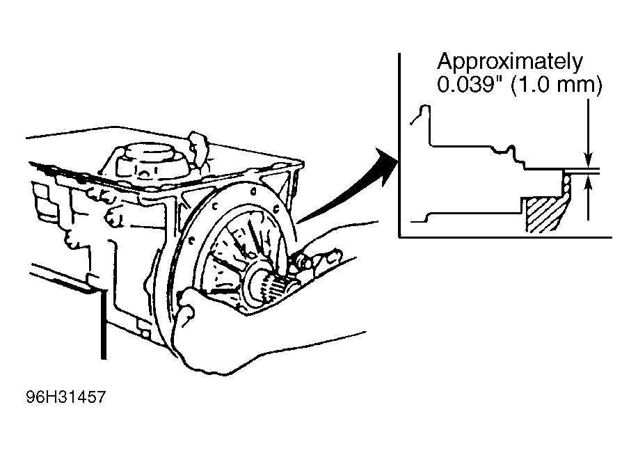
- Measure from transmission case to oil pump surface. See Fig 1
. Ensure height is about .004" (1.0 mm). Install "O" ring on input shaft.
- Install "O" rings on converter housing and apply a small amount of sealer around "O" rings and bolt holes on both sides of torque converter housing. Install torque converter housing. Tighten bolts in a crisscross pattern to specification. See TORQUE SPECIFICATIONS
.
- Install input/turbine speed sensor. Tighten brake band anchor end bolt to 35-52 INCH lbs. (3.9-5.9 N.m) and back off 2 1/2 turns. Install lock nut and tighten to specification.
- Install NEW "O" ring and install vehicle speed sensor. Install output speed sensor. Install "O" ring and install solenoid connector to transmission case.
- Install accumulator springs in correct location. See Figure
. See ACCUMULATORS
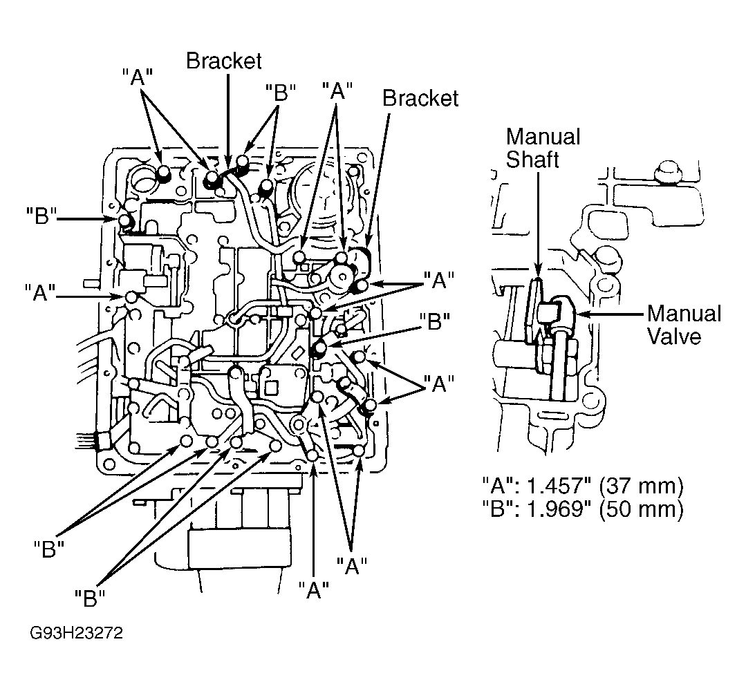
under COMPONENT DISASSEMBLY & REASSEMBLY for spring dimensions. Install valve body assembly. Ensure manual valve engages manual shaft. Install retaining bolts. Ensure correct position of bolts. See Fig 2
. Tighten bolts to specification. See TORQUE SPECIFICATIONS
.
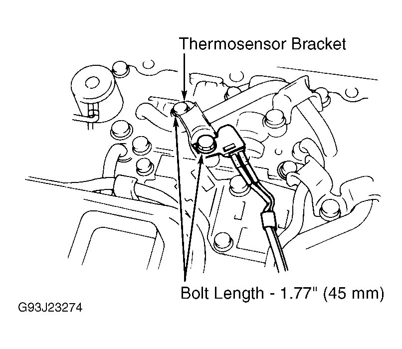
- Install new "O" ring on oil strainer and install oil strainer into transmission. Install TFT sensor. See Fig 3
. Tighten bolts to specification. Mount solenoid wire harness with clips.
 Courtesy of MAZDA MOTORS CORP.
 Courtesy of MAZDA MOTORS CORP.
 Courtesy of MAZDA MOTORS CORP.
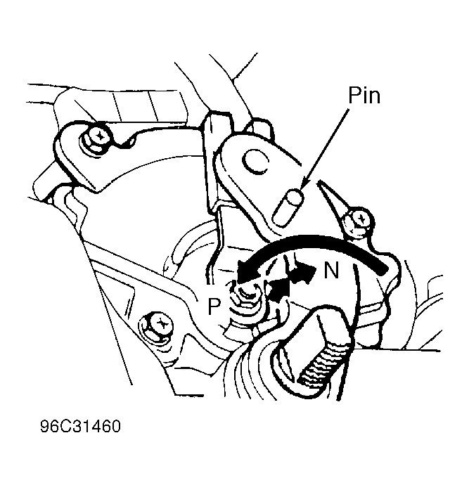
- Place magnet in oil pan. Install oil pan gasket, oil pan and oil pan bolts. Install harness connector bracket (if applicable). Install transmission range switch over manual shaft. Move manual shaft fully rearward. Move manual shaft 2 notches forward ("N" position).
- Insert a .157" (4.00 mm) pin through holes of manual shaft lever and transmission range switch for alignment. See Fig 4
. Tighten switch bolts to specification. See TORQUE SPECIFICATIONS
. Remove alignment pin.
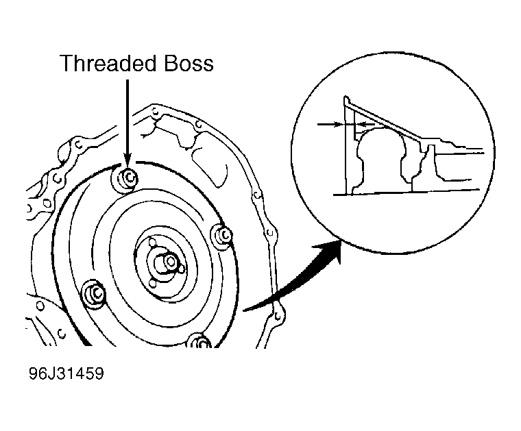
- Set torque converter with hub up and fill with ATF. Install torque converter on input shaft. Ensure torque converter engages notches in oil pump. Measure depth of torque converter housing to threaded boss on torque converter. Depth should be 1.161" (29.50 mm). See Fig 5
. If not, recheck torque converter installation.
 Courtesy of MAZDA MOTORS CORP.
 Courtesy of MAZDA MOTORS CORP.