- Remove the rear case assembly. Refer to
"REAR CASE ".
- Remove the front case assembly. Refer to
"FRONT CASE ".
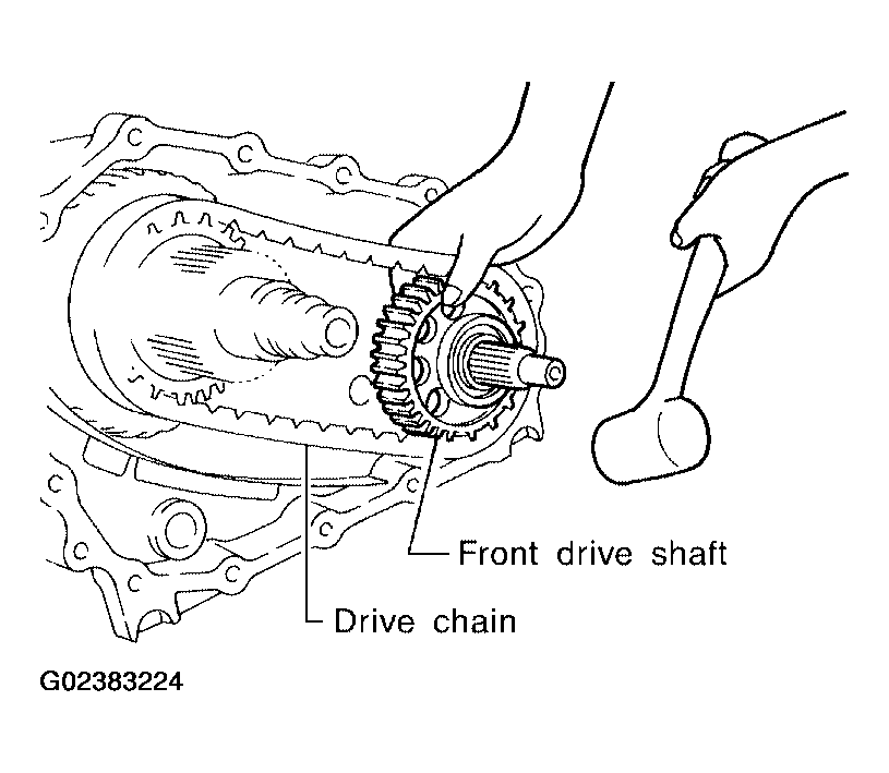
- Hold the front drive shaft with one hand and tap to remove the front drive shaft with the drive chain.
CAUTION:
Do not tap drive chain.
 Courtesy of NISSAN MOTOR CO., U.S.A.
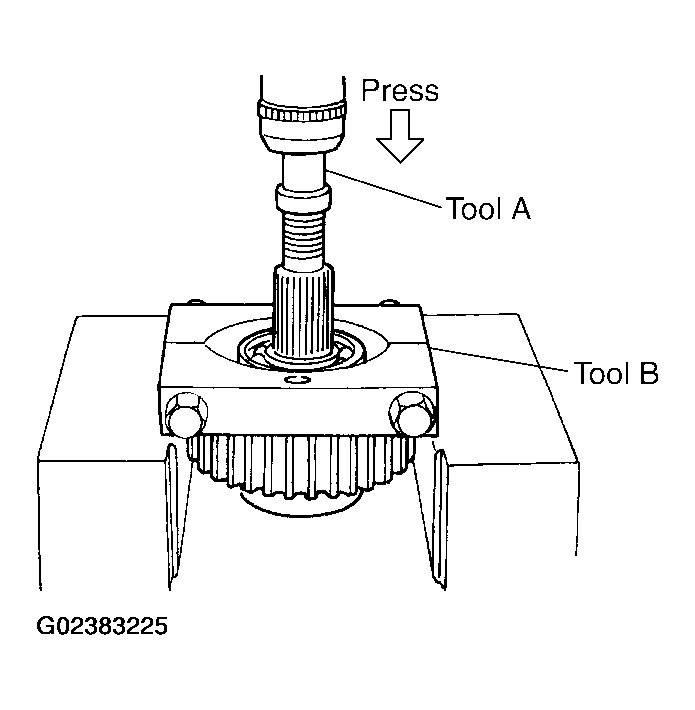
- Remove the front drive shaft front bearing, using Tools.
- Tool number A: ST33052000 ( - )
- B:ST30031000( - )
 Courtesy of NISSAN MOTOR CO., U.S.A.
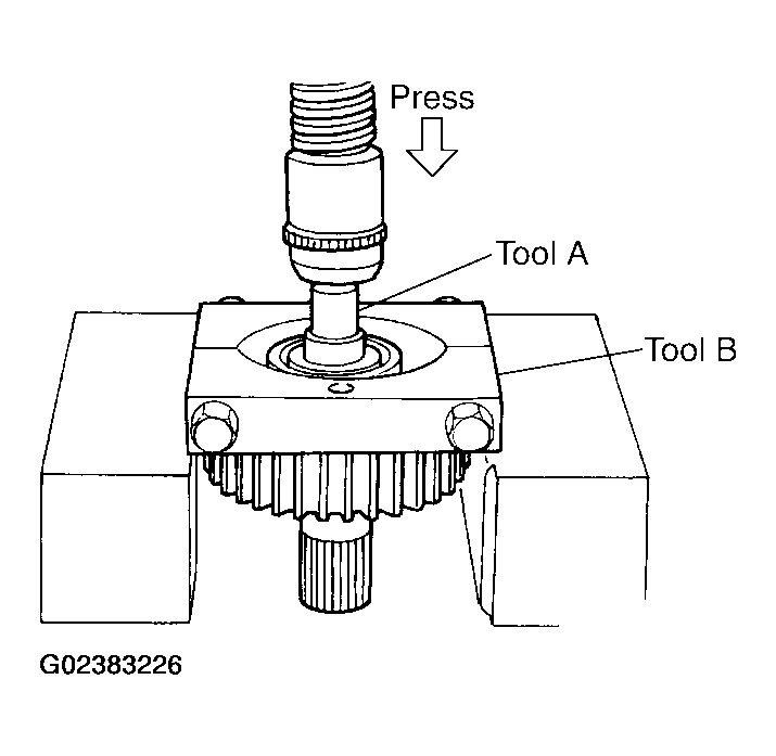
- Remove the front drive shaft rear bearing, using Tools.
- Tool number A: ST33052000 ( - )
- B:ST30031000( - )
 Courtesy of NISSAN MOTOR CO., U.S.A.
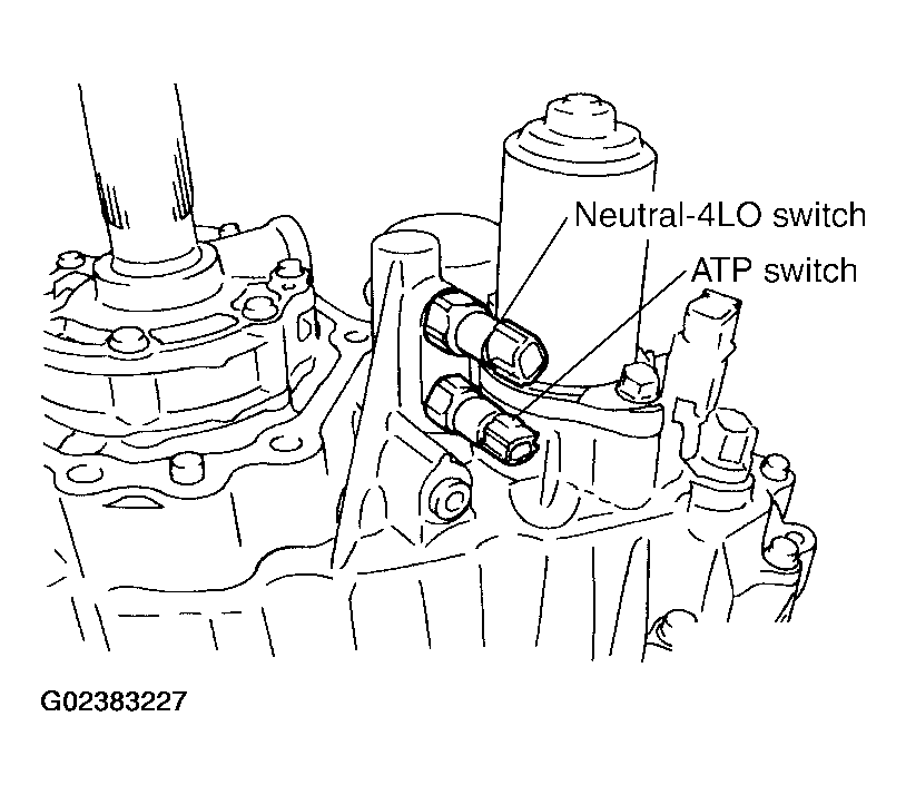
- Remove the neutral-4LO and ATP switches.
 Courtesy of NISSAN MOTOR CO., U.S.A.
- Remove the bolts and main oil pump.
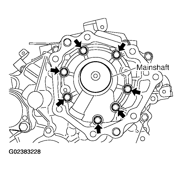 Courtesy of NISSAN MOTOR CO., U.S.A.
- Remove the outer gear and inner gear from the main oil pump housing.
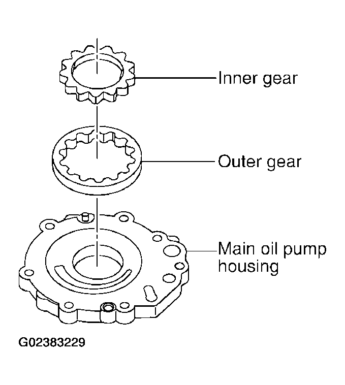 Courtesy of NISSAN MOTOR CO., U.S.A.
- Remove the seal ring from the main oil pump cover.
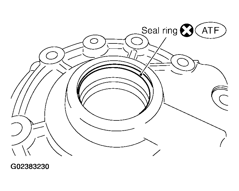 Courtesy of NISSAN MOTOR CO., U.S.A.
- Remove the stem bleeder from the bleed hole.
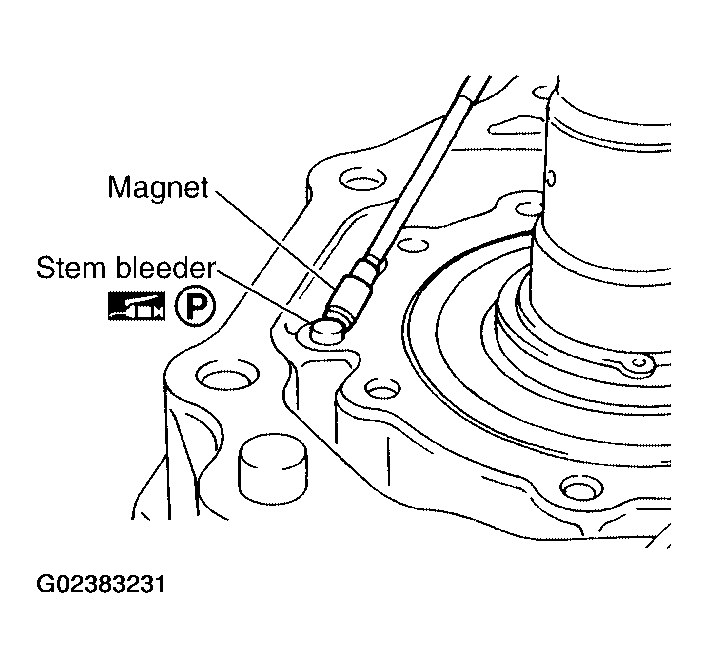 Courtesy of NISSAN MOTOR CO., U.S.A.
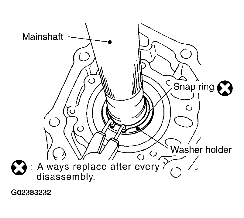
- Remove the snap ring and washer holder from the mainshaft.
 Courtesy of NISSAN MOTOR CO., U.S.A.
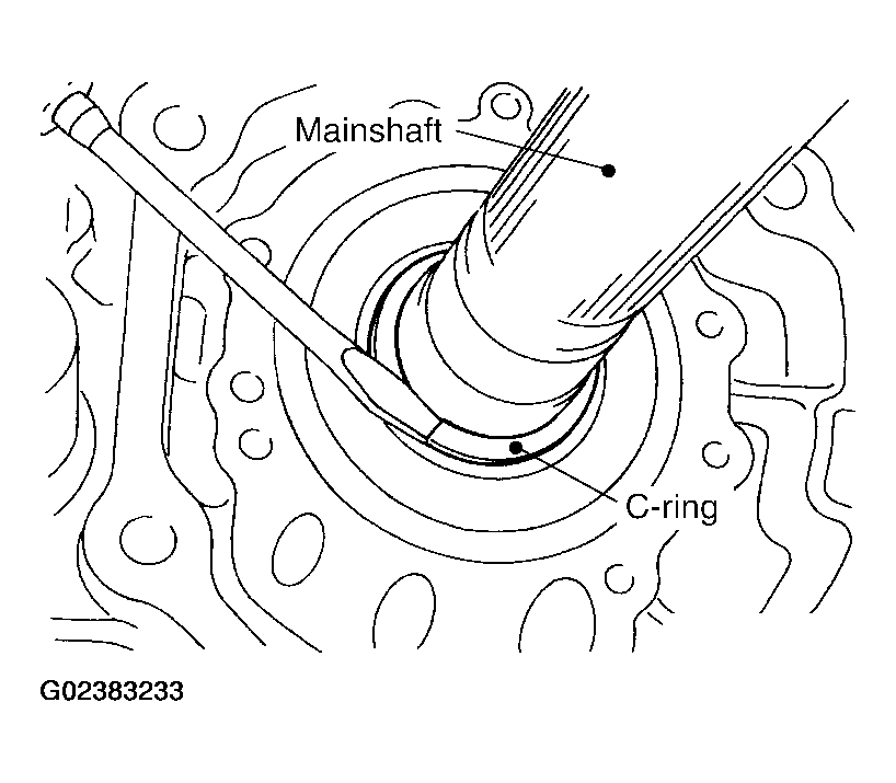
- Remove the C-rings from the mainshaft, using suitable tool.
 Courtesy of NISSAN MOTOR CO., U.S.A.
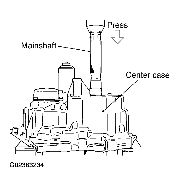
- Set the center case on the press stand. Remove the mainshaft from the center case.
 Courtesy of NISSAN MOTOR CO., U.S.A.
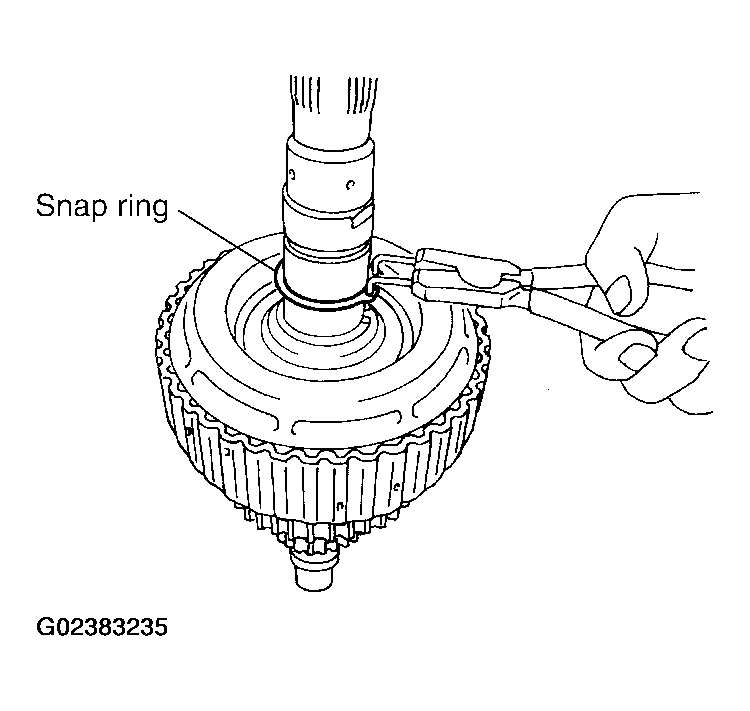
- Remove the snap ring from the mainshaft, using suitable tool.
 Courtesy of NISSAN MOTOR CO., U.S.A.
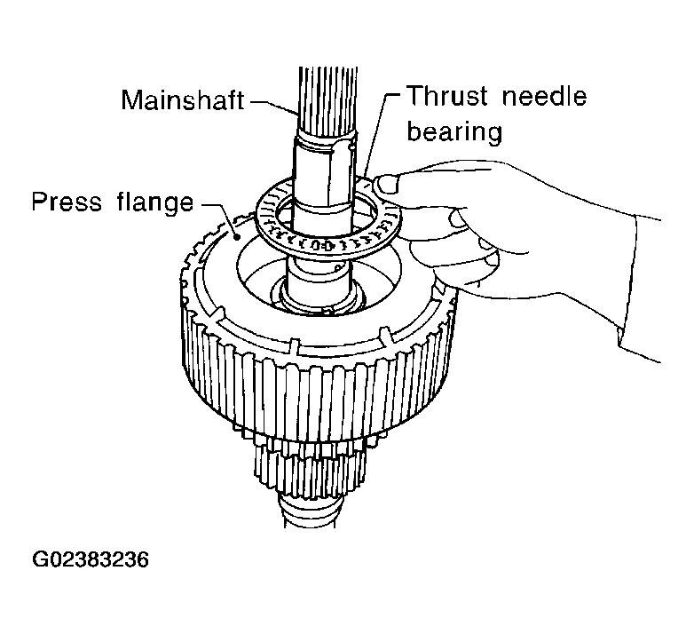
- Remove the thrust needle bearing from the press flange.
 Courtesy of NISSAN MOTOR CO., U.S.A.
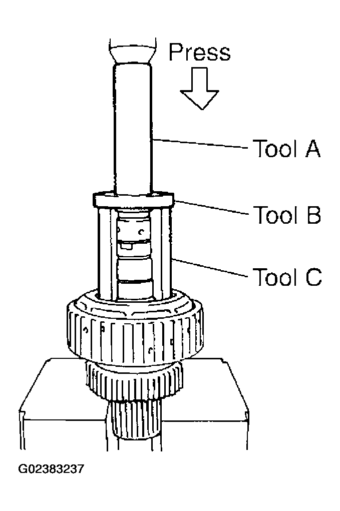
- Press the flange until the snap ring is out of place, using Tools.
- Tool number A: ST22452000 (J-34335)
- B:ST30911000( - )
- C: KV31103300 ( - )
 Courtesy of NISSAN MOTOR CO., U.S.A.
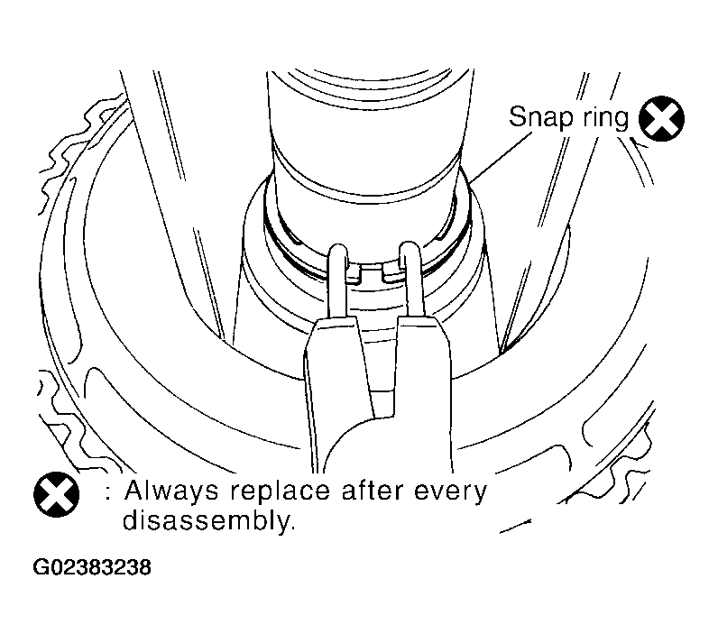
- Remove the snap ring from the mainshaft, using suitable tool.
 Courtesy of NISSAN MOTOR CO., U.S.A.
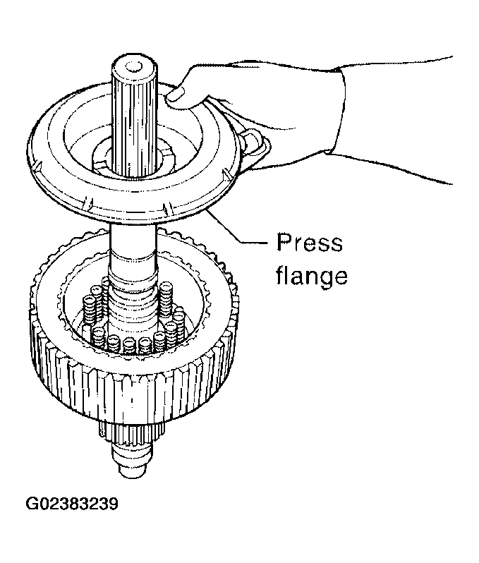
- Remove the press flange from the mainshaft.
 Courtesy of NISSAN MOTOR CO., U.S.A.
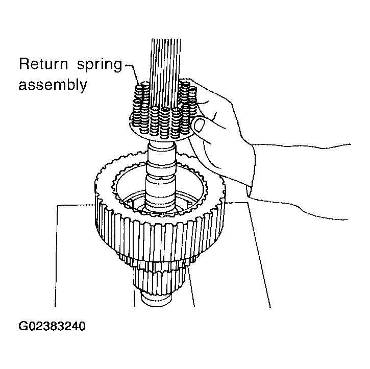
- Remove the return spring assembly from the clutch hub.
 Courtesy of NISSAN MOTOR CO., U.S.A.
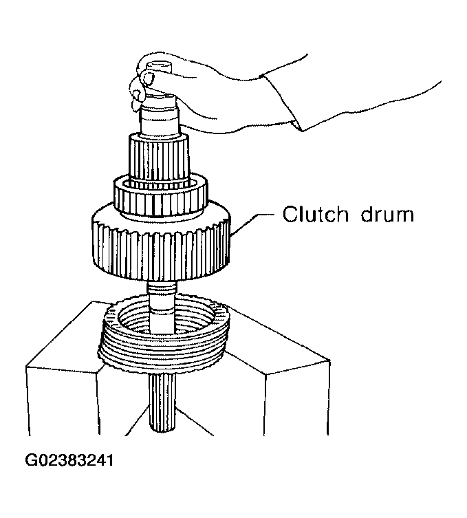
- Remove each plate from the clutch drum.
 Courtesy of NISSAN MOTOR CO., U.S.A.
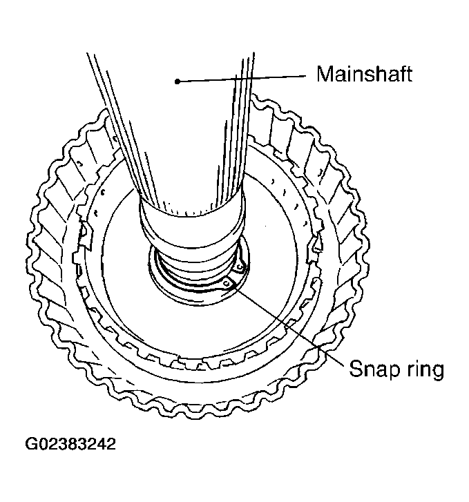
- Remove the snap ring from the mainshaft.
 Courtesy of NISSAN MOTOR CO., U.S.A.
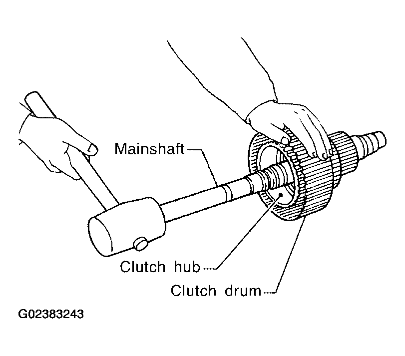
- Remove the mainshaft from the clutch drum and clutch hub, using suitable tool.
- Remove the needle bearing and spacer from the mainshaft.
 Courtesy of NISSAN MOTOR CO., U.S.A.
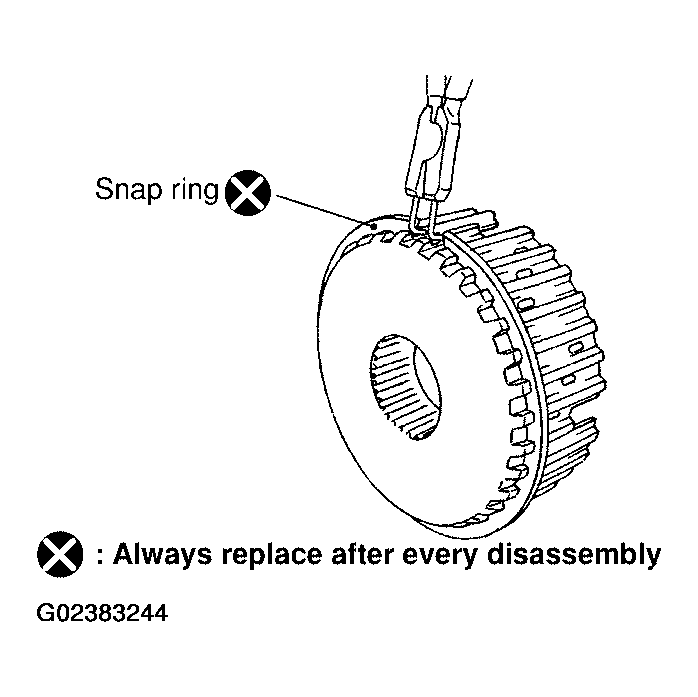
- Remove the snap ring from the clutch hub, using suitable tool.
 Courtesy of NISSAN MOTOR CO., U.S.A.
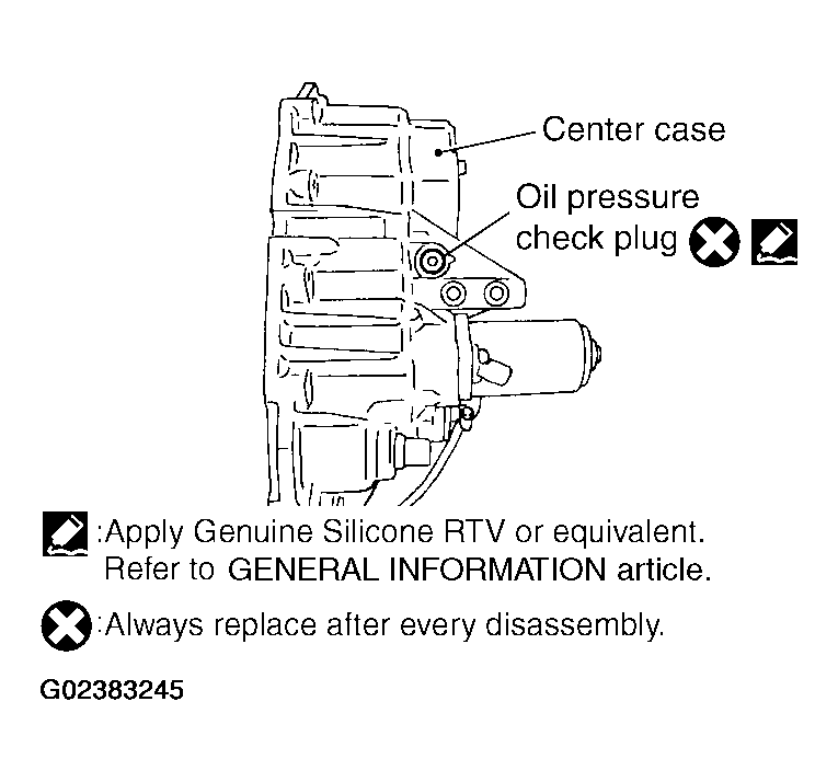
- Remove the oil pressure check plug from the oil pressure check port.
 Courtesy of NISSAN MOTOR CO., U.S.A.
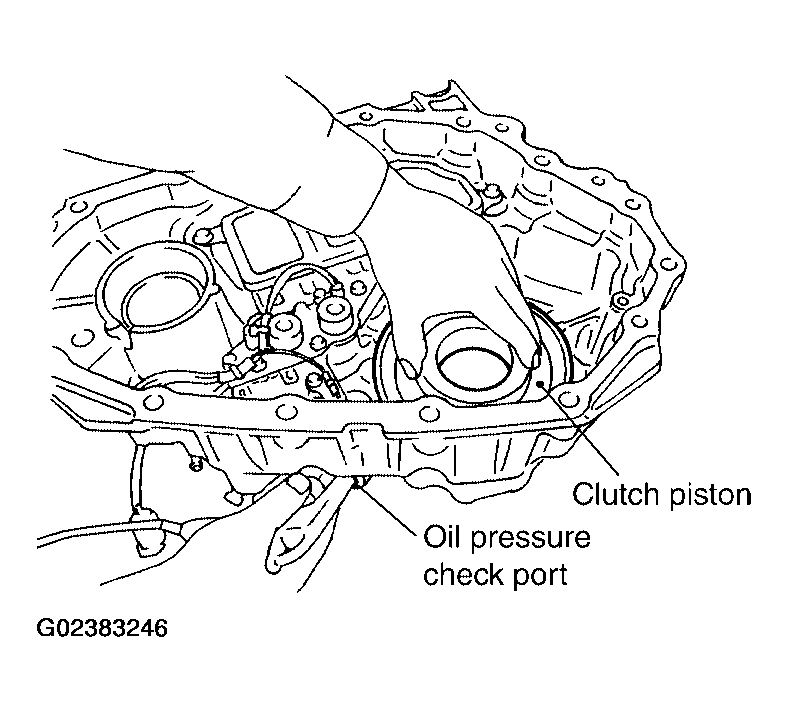
- Apply air gradually from the oil pressure check port, and remove the clutch piston assembly from the center case.
 Courtesy of NISSAN MOTOR CO., U.S.A.
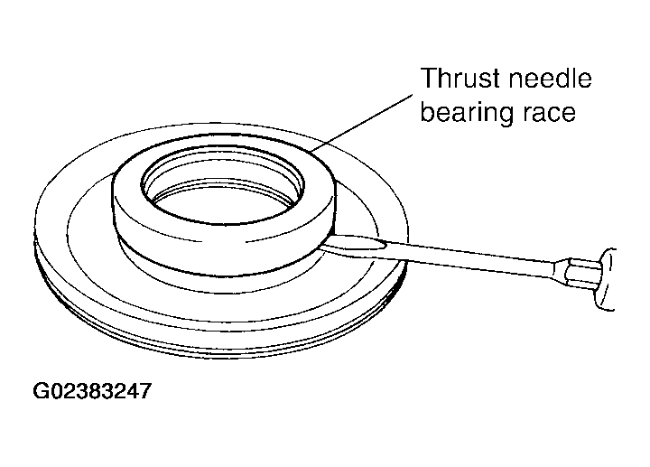
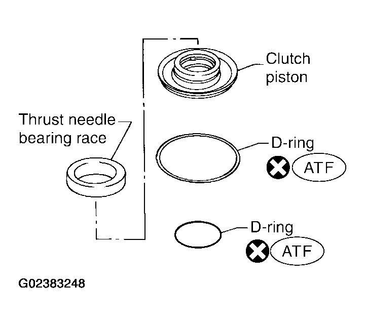
- Remove the thrust needle bearing race from the clutch piston by hooking a edge into 3 notches of the thrust needle bearing race, using suitable tool.
CAUTION:
Do not damage clutch piston or thrust needle bearing race.
 Courtesy of NISSAN MOTOR CO., U.S.A.
- Remove the two D-rings from the clutch piston.
 Courtesy of NISSAN MOTOR CO., U.S.A.
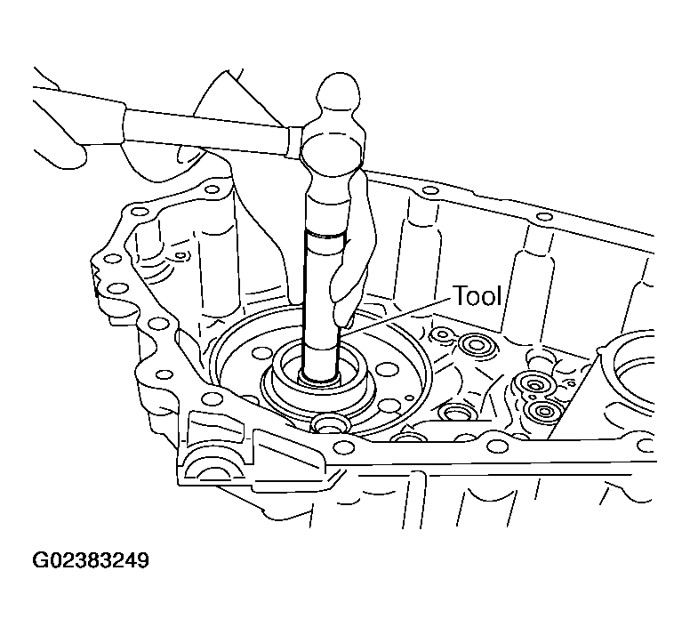
- Remove the mainshaft rear bearing from the center case, using Tool.
- Tool number: KV38100300 (J-25523)
 Courtesy of NISSAN MOTOR CO., U.S.A.
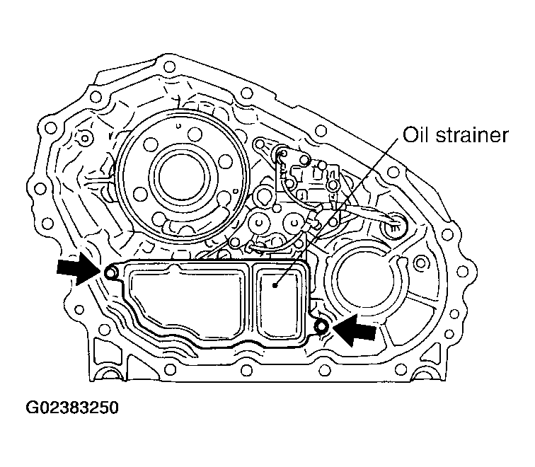
- Remove the two bolts and oil strainer.
 Courtesy of NISSAN MOTOR CO., U.S.A.
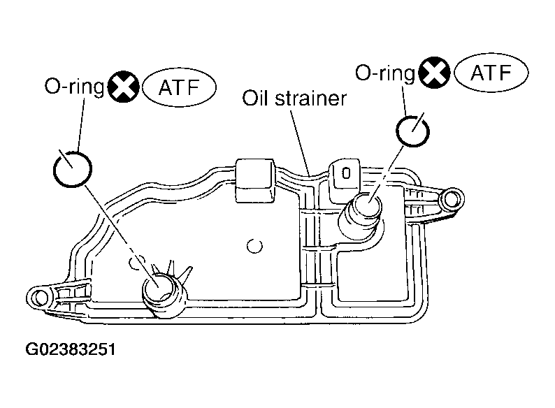
- Remove the two O-rings from the oil strainer.
 Courtesy of NISSAN MOTOR CO., U.S.A.
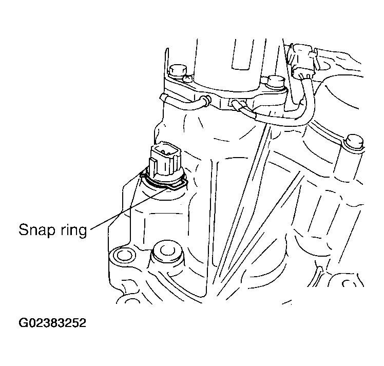
- Remove the snap ring. Then push the connector assembly into the center case to remove the control valve assembly.
 Courtesy of NISSAN MOTOR CO., U.S.A.
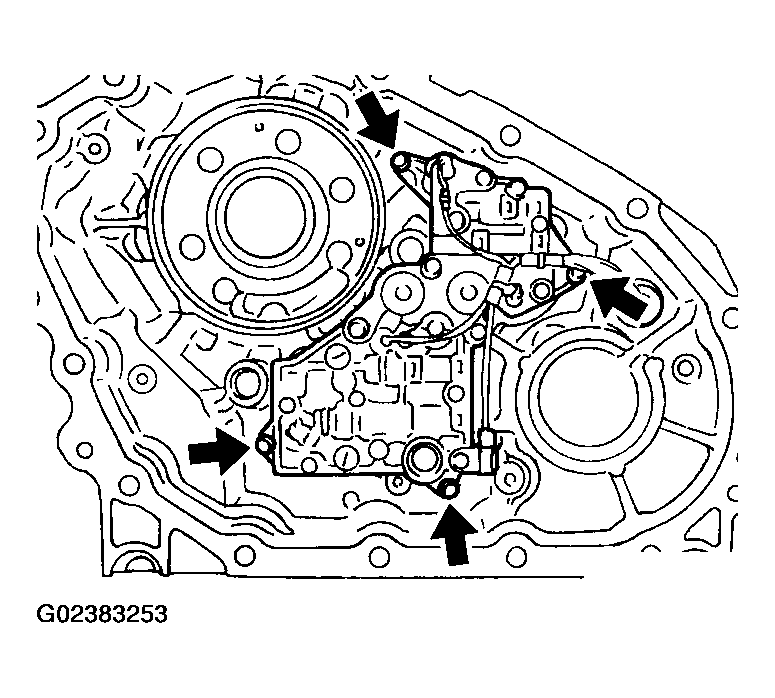
- Remove the control valve assembly bolts.
- Remove the control valve assembly.
CAUTION:
- Do not reuse any part that has been dropped or damaged.
- Make sure valve is assembled in the proper direction.
- Do not use a magnet because residual magnetism stays during disassembly.
 Courtesy of NISSAN MOTOR CO., U.S.A.
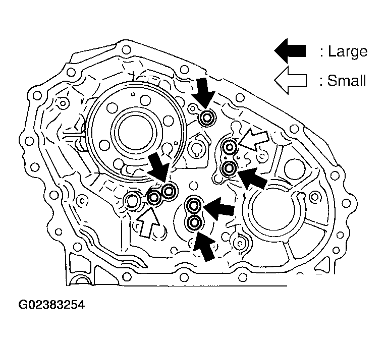
- Remove the lip seals from the center case.
CAUTION:
There are two kinds of lip seals (lip seal of large inner diameter: 5 pieces, lip seal of small inner diameter: 2 pieces). Confirm the position before disassembly.
 Courtesy of NISSAN MOTOR CO., U.S.A.
- Disassemble the control valve assembly with the following procedure.
CAUTION:
- Do not reuse any part that has been dropped or damaged.
- Make sure valve is assembled in the proper direction.
- Do not use a magnet because residual magnetism stays during disassembly.
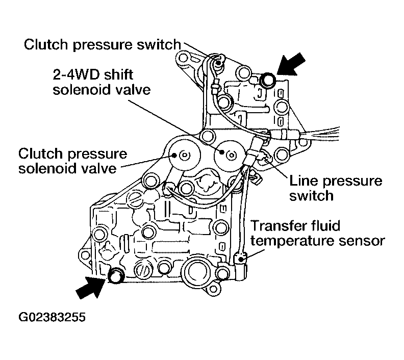
- Remove all the bolts except for the two shown.
 Courtesy of NISSAN MOTOR CO., U.S.A.
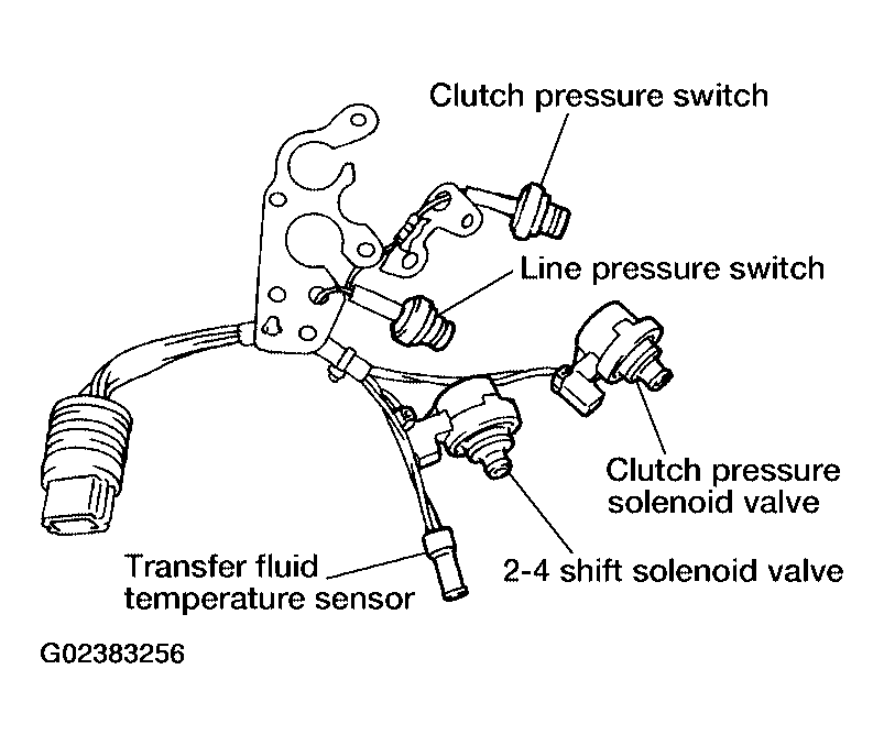
- Remove the following from the control valve assembly:
- Clutch pressure solenoid valve
- Clutch pressure switch
- 2-4WD shift solenoid valve
- Line pressure switch
- Transfer fluid temperature sensor
- Remove the O-rings from each solenoid valve, switch and terminal body.
 Courtesy of NISSAN MOTOR CO., U.S.A.
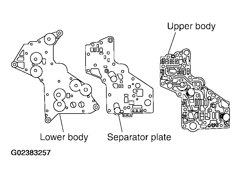
- Place the control valve with the lower body facing up. Remove the two bolts, and then remove the lower body and separator plate from the upper body.
CAUTION:
Do not drop relief balls. Detach lower body carefully.
 Courtesy of NISSAN MOTOR CO., U.S.A.
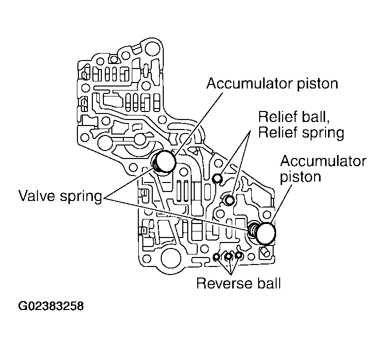
- Make sure the reverse balls, relief balls, relief springs, accumulator pistons and valve springs are securely installed as shown, and remove them.
 Courtesy of NISSAN MOTOR CO., U.S.A.
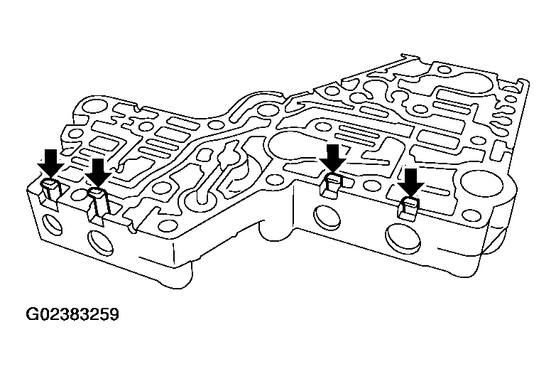
- Remove the retainer plates.
 Courtesy of NISSAN MOTOR CO., U.S.A.
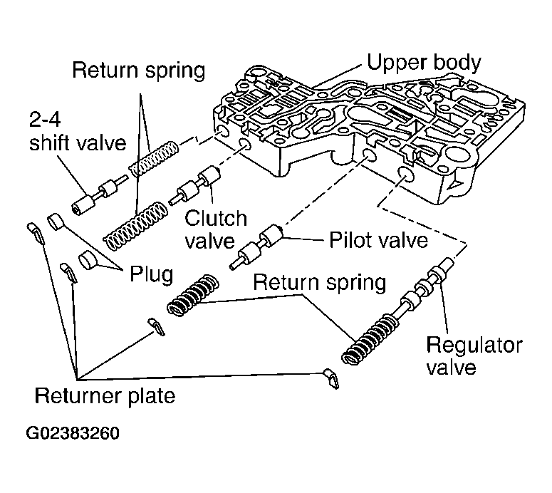
- Remove each control valve, spring and plug.
 Courtesy of NISSAN MOTOR CO., U.S.A.
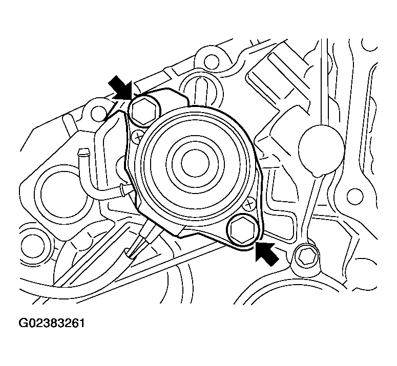
- Remove the transfer motor bolts and motor from the center case. Then remove the O-ring from the transfer motor.
 Courtesy of NISSAN MOTOR CO., U.S.A.
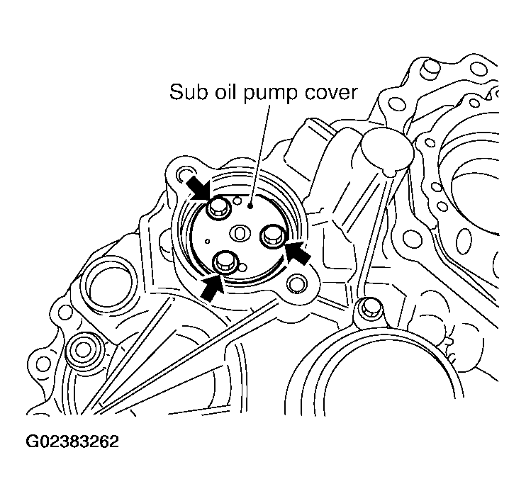
- Remove the sub oil pump cover bolts.
 Courtesy of NISSAN MOTOR CO., U.S.A.
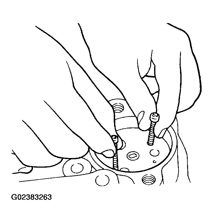
- Thread two bolts (M4 x 0.8) into the holes of sub oil pump cover as shown, and pull out to remove the sub oil pump assembly.
 Courtesy of NISSAN MOTOR CO., U.S.A.
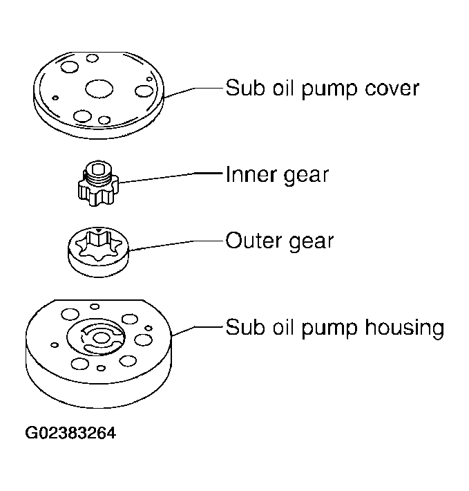
- Remove the outer gear and inner gear from the sub oil pump housing.
 Courtesy of NISSAN MOTOR CO., U.S.A.
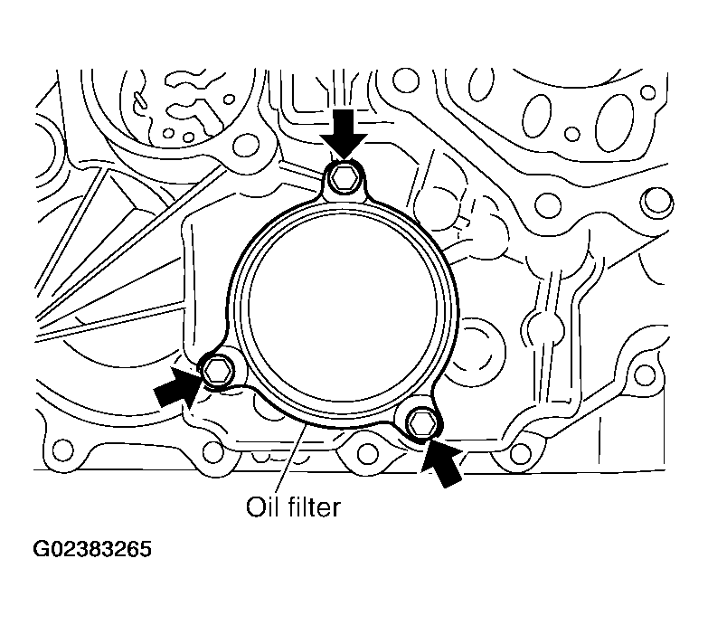
- Remove the oil filter bolts and oil filter.
CAUTION:
- Do not damage center case and oil filter.
- Loosen bolts and detach oil filter evenly.
 Courtesy of NISSAN MOTOR CO., U.S.A.
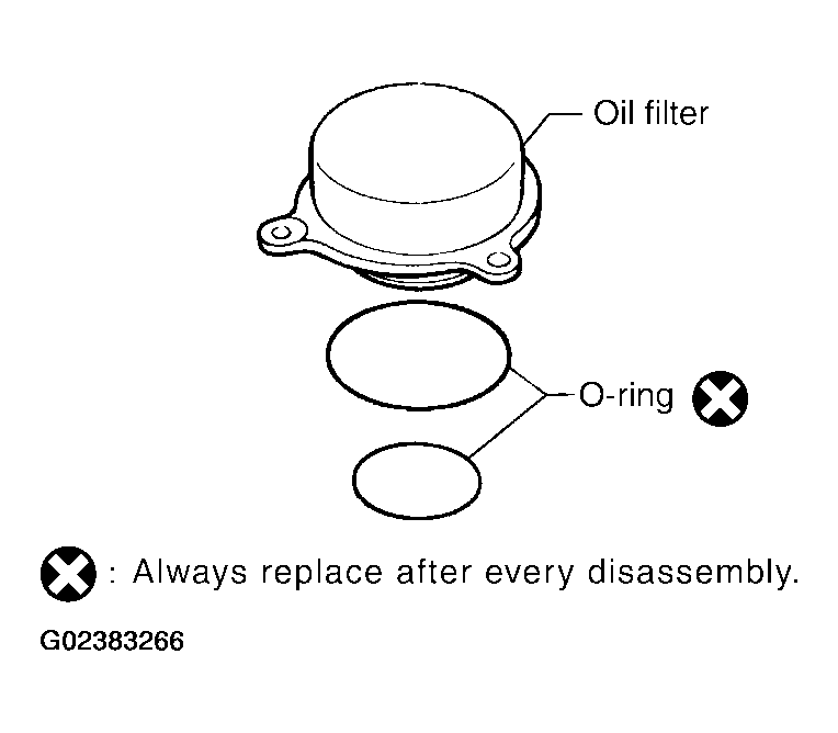
- Remove the O-rings from the oil filter.
 Courtesy of NISSAN MOTOR CO., U.S.A.
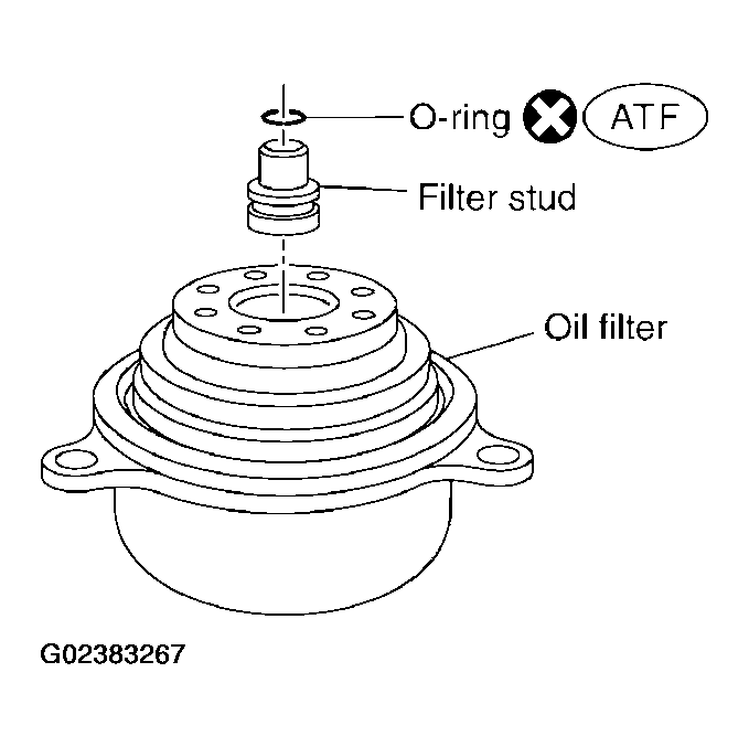
- Remove the oil filter stud from the oil filter.
- Remove the O-ring from the oil filter stud.
 Courtesy of NISSAN MOTOR CO., U.S.A.