Rectifier Assembly Test
- Remove rectifier assembly from alternator. Set ohmmeter to "x1" range. To test positive set of diodes, connect one ohmmeter probe to "B+" terminal and contact each of 3 stator lead terminals with other probe. See Fig 1.
- Reverse probes and repeat test. All diodes should show readings of about 7 ohms resistance in one direction and infinite readings with probes reversed.
- Repeat test for negative set of diodes by connecting one probe to rectifier assembly base plate and contacting each of 3 stator lead terminals with other probe. See Fig 1. If meter readings are not as specified in step 2), replace rectifier assembly.
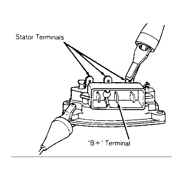 Courtesy of FORD MOTOR CO.