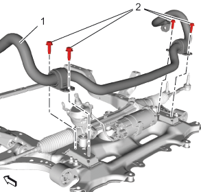
- Stabilizer Shaft (1)» Install
 Courtesy of GENERAL MOTORS COMPANY
- Bolt (2)» Install NEW bolts. [4x]
- First Pass: 22 N.m (16 lb ft)
- Final Pass: 30-45 degrees Use the special tool: EN-45059
meter
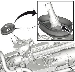
- Make sure the notch in the steering column dash outer seal (1) is still correctly aligned to the nose on the electric belt drive rack and pinion steering gear.
 Courtesy of GENERAL MOTORS COMPANY
- Raise the drivetrain and front suspension frame cradle until a distance to the vehicle of 136 mm (5.35 in).
- Raise the drivetrain and front suspension frame cradle to the vehicle.
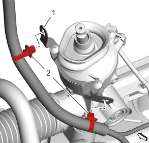
- Retainer (2) @ Cable Bracket (1)» Install [2x]
 Courtesy of GENERAL MOTORS COMPANY
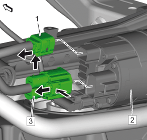
- Electrical Connector (1) @ Power Steering Assist Motor (2)» Connect
 Courtesy of GENERAL MOTORS COMPANY
NOTE:
Raise the drivetrain and the front suspension cradle as necessary.
- Electrical Connector (1) @ Power Steering Assist Motor (3)» Connect
- Steering Gear Heat Shield» Install - Steering Gear Heat Shield Replacement
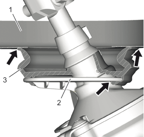
- Make sure the steering column dash outer seal (3) fits correctly on the electric belt drive rack and pinion steering gear (2). See arrows.
 Courtesy of GENERAL MOTORS COMPANY
- Make sure the steering column dash outer seal fits correctly on the dash panel front lower cross bar (1). See arrows.
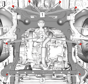
- Drivetrain and Front Suspension Cradle Rear Bolt (1)» Install [4x] - Install NEW bolts. - Do NOT tighten.
 Courtesy of GENERAL MOTORS COMPANY
- Drivetrain and Front Suspension Cradle Front Bolt (2)» Install [2x] - Install NEW bolts. - Do NOT tighten.
- Drivetrain and Front Suspension Crossmember Extension Bolt (3)» Install [2x] - Do NOT tighten.
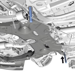
- Make sure the drivetrain and front suspension cradle (1) fits closely to the vehicle.
 Courtesy of GENERAL MOTORS COMPANY
- Guide the 2 CH-51034
pins (2) through the bores of the drivetrain and front suspension cradle into the underbody.
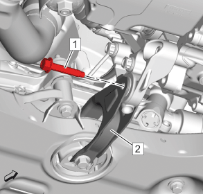
- Transmission Mount Strut Bolt (1) @ Transmission Mount Strut (2)» Install NEW bolts. - Do NOT tighten.
 Courtesy of GENERAL MOTORS COMPANY
- Drivetrain and Front Suspension Cradle Rear Bolt (1)» Tighten [4x]
Courtesy of GENERAL MOTORS COMPANY
- First Pass: 100 N.m (74 lb ft)
- Final Pass: 90-105 degrees. Use the special tool: EN-45059
meter
- Drivetrain and Front Suspension Cradle Front Bolt (2)» Tighten [2x]
- First Pass: 100 N.m (74 lb ft)
- Final Pass: 90-105 degrees. Use the special tool: EN-45059
meter
- Drivetrain and Front Suspension Crossmember Extension Bolt (3)» Tighten [2x] 58 N.m (43 lb ft)
- CH-51034
Pin» Remove [2x]
- Transmission Mount Strut Bolt (1) @ Transmission Mount Strut (2)» Install and tighten - Install NEW bolts.
Courtesy of GENERAL MOTORS COMPANY
- First Pass: 100 N.m (74 lb ft)
- Final Pass: 90-105 degrees. Use the special tool: EN-45059
meter
- Exhaust Muffler Insulator Nut (1)» Tighten 22 N.m (16 lb ft) [2x]
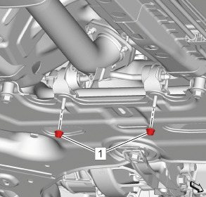 Courtesy of GENERAL MOTORS COMPANY
- Stabilizer Shaft Link (1) @ Stabilizer Shaft (3)» Connect
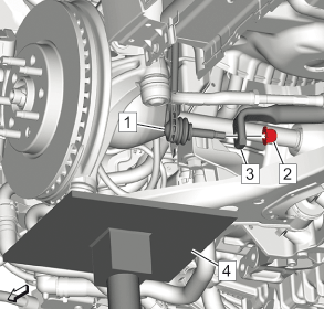 Courtesy of GENERAL MOTORS COMPANY
- Stabilizer Shaft Link Nut (2) @ Stabilizer Shaft Link (1)» Install and tighten 65 N.m (48 lb ft) [2x] - Install NEW nuts.
- Connect the outer tie rods to the steering knuckles. (3) [2x]
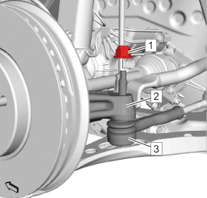 Courtesy of GENERAL MOTORS COMPANY
- Install a NEW steering linkage outer tie rod nut. (1) [2x]
NOTE:
Support the steering linkage outer tie rod joint with a hydraulic jack.
- First Pass: 35 N.m (26 lb ft)
- Final Pass: 30-45 degrees. Use the special tool: EN-45059
meter
- Install the lower control arm ball joint to the steering knuckle.
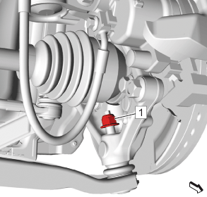 Courtesy of GENERAL MOTORS COMPANY
NOTE:
Support the lower control arm ball joint with a hydraulic jack.
NOTE:
Hold against the hex of the threaded stud to tighten the nut (1).
- Nut (1) Install and tighten [2x]
- First Pass: 35 N.m (26 lb ft)
- Final Pass: 30-45 degrees. Use the special tool: EN-45059
meter
- {If equipped} Front Compartment Splash Shield» Install - Front Compartment Splash Shield Replacement
- {If equipped} Front Compartment Air Deflector» Install - Front Compartment Air Deflector Replacement
- {If equipped} Front Compartment Insulator» Install - Front Compartment Insulator Replacement
- Front Bumper Fascia Extension» Install - Front Bumper Fascia Extension Replacement
- Install the front tire and wheel assemblies. Refer to Tire and Wheel Removal and Installation
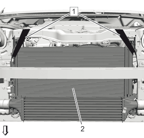
- Detach the radiator (2) from the front end upper tie bar.
 Courtesy of GENERAL MOTORS COMPANY
NOTE:
Graphic shows the vehicle front without bumper for the sake of clarity.
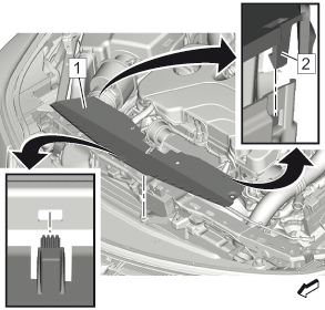
- Install the radiator air upper deflector (1).
 Courtesy of GENERAL MOTORS COMPANY
- Clip in the 2 clips (2).
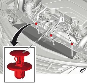
- Retainer (1)» Install [3x]
 Courtesy of GENERAL MOTORS COMPANY
- Retainer (1)» Install [3x]
- Steering Column Dash Inner Seal» Install - Steering Column Dash Inner Seal Replacement
- Connect the steering intermediate shaft to the steering gear. Refer to Intermediate Steering Shaft Replacement
- Battery Negative Cable» Connect - Battery Negative Cable Disconnection and Connection
- Measure and adjust the wheel alignment. Refer to Wheel Alignment Measurement