Variable Effort Steering (VES) System Function Test
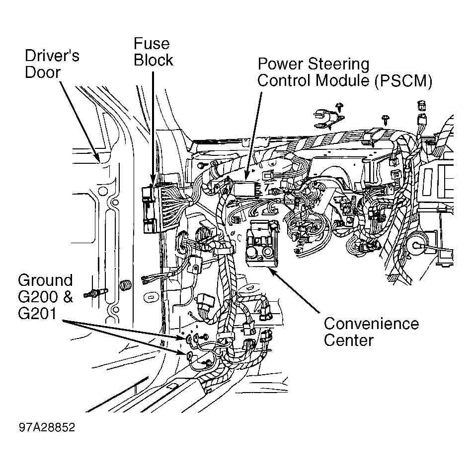
- Disconnect electrical connector from Power Steering Control Module (PSCM). The PSCM is located to the left of steering column, near firewall and contains a Black 8-Pin electrical connector. See Fig 1.
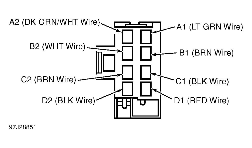
- Remove Dark Green/White wire from terminal A2 on the electrical connector for PSCM. See Fig 2. A jumper wire is to be installed in place of Dark Green/White wire on the electrical connector. Install a electrical connector terminal Part No. 12015870 on a one foot long jumper wire made of 18 guage wire. Install electrical connector terminal on jumper wire in cavity on electrical connector for PSCM.
- Strip remaining end of jumper wire and connect to Red lead on Signal Generator (J-38522). Clip Black lead of signal generator to a good ground. Reinstall electrical connector on PSCM. Connect Tech 1 scan tool to Data Link Connector (DLC). The DLC is attached to instrument panel at right side of steering column.
- Install cartridge for Anti-Lock Brake System (ABS) in Tech 1 scan tool. Select VES DUTY CYCLE TEST on Tech 1 scan tool. Ensure signal generator is not plugged in at this time.
- Start engine. With engine idling, rotate steering wheel in half turns quickly to the left and right 3 times while noting duty cycle on Tech 1 scan tool and amount of power steering assist. No change in duty cycle should exist and full power steering assist should exist with no lag or decrease in the assist. Go to next step.
- Plug in signal generator. Set signal generator for a 5-volt square wave at 30 Hz with a 50 percent duty cycle. Duty cycle should increase to approximately 42-52 percent. Go to next step.
- Increase frequency on signal generator to 60 Hz. Duty cycle should now increase to approximately 57-67 percent. Go to next step.
- Rotate steering wheel in half turns quickly to the left and right 3 times while noting duty cycle on Tech 1 scan tool and amount of power steering assist. Duty cycle should decrease rapidly and return to the previous duty cycle with a low of approximately 35-45 percent. A noticeable decrease in power steering assist should exist at the beginning of the turns. Go to next step.
- If VES system operates correctly in all previous steps, the system is operating properly. If VES system operates incorrectly in any of the previous steps, go to next step.
- Turn engine off. Unplug signal generator. Install power steering pressure tester using proper procedure for checking power steering pump pressure. See TESTING under LUBRICATION in STEERING SYSTEM - POWER RECIRCULATING BALL
article. Start engine and warm engine to normal operating temperature.
- Allow engine to idle while noting duty cycle and power steering pump pressure. Duty cycle should be approximately 20-30 percent and power steering pump pressure should be approximately 150 psi (10.5 kg/cm2
).
- Plug in signal generator. Set signal generator for a 5-volt square wave at 60 Hz with a 50 percent duty cycle. Duty cycle should increase to approximately 57-67 percent and power steering pump pressure should decrease to approximately 50 psi (3.5 kg/cm2
). Shut engine off.
 Courtesy of GENERAL MOTORS CORP.
 Courtesy of GENERAL MOTORS CORP.