TCM Wiring Circuits
If component and/or circuit fault is diagnosed, check appropriate circuit between component and TCM connector terminal(s). Repair as necessary. If component and circuits are okay, replace TCM. For TCM connector terminal locations, See Fig 2. For TCM connector terminal identification, see TCM CONNECTOR TERMINAL IDENTIFICATION table.
TCM CONNECTOR TERMINAL IDENTIFICATION
| Terminal No. |
Component |
| Connector "A" |
| 1 |
RPM/Speed Sensor |
| 2 |
RPM/Speed Sensor Ground |
| 3 |
Gear Position Sensor |
| 4 |
Gear Position Sensor |
| 5 |
Gear Position Sensor |
| 6 |
Gear Position Sensor |
| 9 |
Lock-Up Solenoid |
| 10 |
Battery Power |
| 11 |
Vehicle Speed Sensor (VSS) Signal |
| 12 |
VSS Ground Signal |
| 14 |
Oil Temperature Sensor Signal |
| 15 |
Oil Temperature Sensor Ground Signal |
| 20 |
TCM Signal Ground |
| 22 |
Solenoid STH Control Signal |
| 23 |
Solenoid STH Ground Signal |
| 27 |
Shift Solenoid S1 Control Signal |
| 28 |
Shift Solenoid S2 Control Signal |
| 29 |
Power Ground |
| 30 |
Battery Voltage From Ignition Switch |
| Connector "B" |
| 1 |
Turbo Torque Control Signal To ECM |
| 2 |
TC1 Torque Control Signal To ECM |
| 3 |
TC2 Torque Control Signal To ECM |
| 4 |
Torque Control Acknowledge Signal From TCM |
| 7 |
Warning Indicator Light Control Signal |
| 12 |
Engine Load Signal From ECM |
| 14 |
Gear Position Sensor Signal |
| 15 |
MIL Request Signal To ECM |
| 16 |
Mode Selector Switch (MS2) |
| 17 |
Mode Selector Switch (MS1) |
| 20 |
TP Sensor Signal From ECM |
| 26 |
Brake Light Switch Signal |
| 30 |
Kickdown Switch Signal |
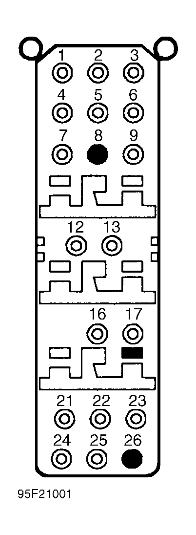 Courtesy of VOLVO CARS OF NORTH AMERICA.
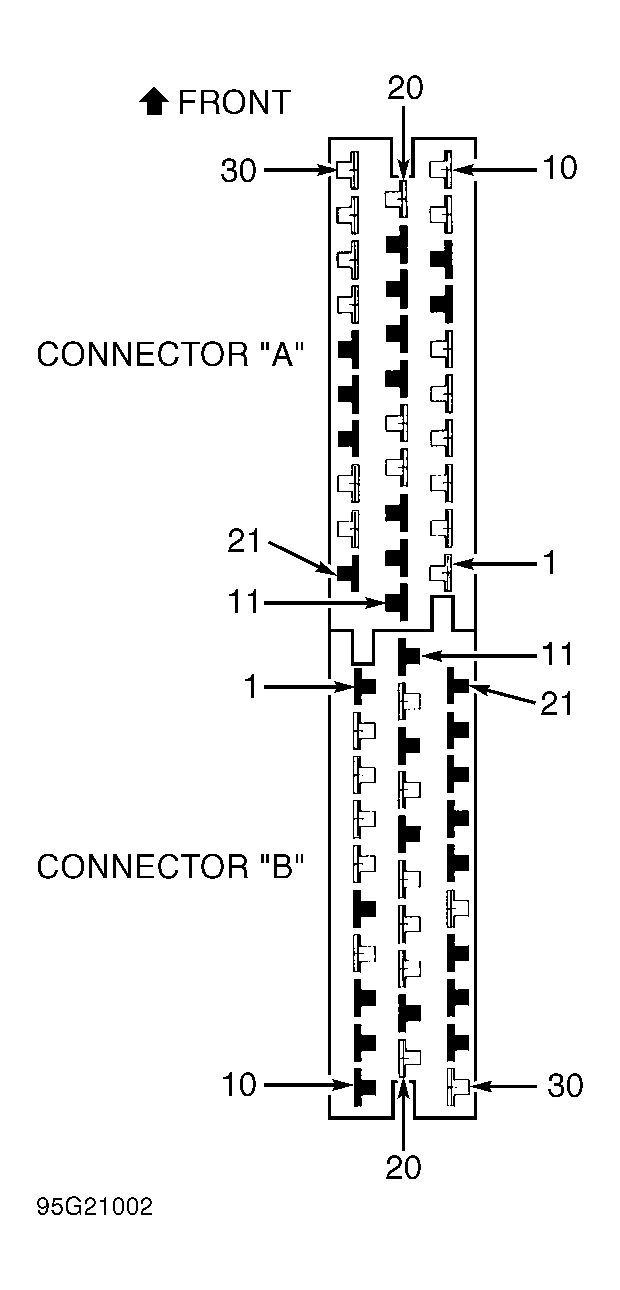 Courtesy of VOLVO CARS OF NORTH AMERICA.