Central Locking System Completely Inoperable
- Turn ignition off. Check that fuse No. 1 is good. Replace fuse as necessary, then go to next step. If fuse is okay, check if fuses No. 2 and 11 in central fuse module are okay. Replace as necessary. If fuses are okay, check voltage supply leads to each fuse. Repair as necessary. If voltage supply to each fuse is okay, go to next step.
- Ensure ignition is off. Determine if front door and trunk/tailgate can be unlocked and locked using key. Check if rear door can be unlocked by pulling up inside door lock buttons and/or opening them using inside door handles. If any central locking module will not work, fault is mechanical. Repair as necessary. If all central locking modules work mechanically, go to next step.
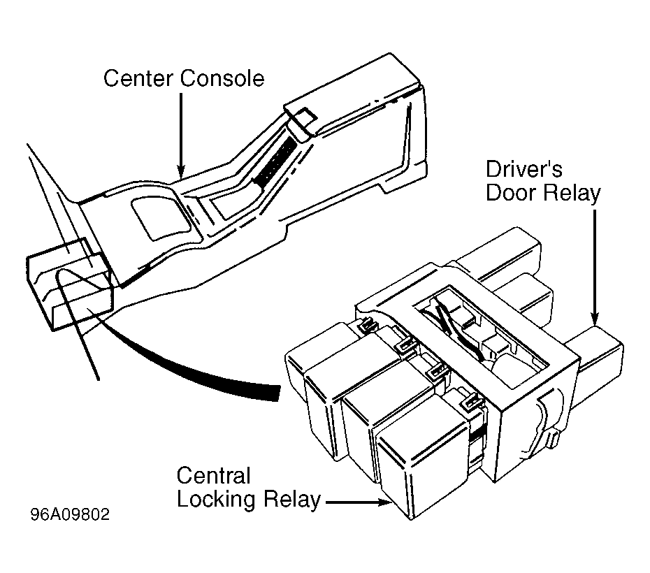
- Ensure ignition is off. Remove central locking relay and driver's door relay. See Fig 1
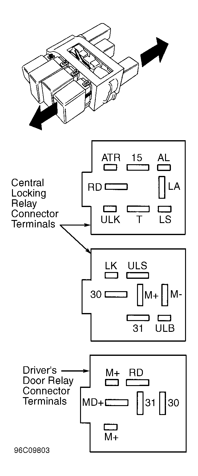
. Connect ohmmeter between central locking relay connector terminal No. 31 and ground, and between driver's door relay terminal No. 31 and ground. See Fig 2
. If ohmmeter reads about zero ohms in both cases, go to next step. If ohmmeter does not read about zero ohms in both cases, check for open or short circuit in ground.
 Courtesy of VOLVO CARS OF NORTH AMERICA.
 Courtesy of VOLVO CARS OF NORTH AMERICA.
- Ensure ignition is off. Connect voltmeter between central locking relay connector terminal No. 30 and driver's door relay connector terminal No. 31. See Fig 2
. If battery voltage is present, go to next step. If battery voltage is not present, check for open or short circuit to ground in power supply.
- Ensure ignition is off. Connect voltmeter between central locking relay connector terminals No. 15 and 31. See Fig 2
. Voltmeter should read about zero volts. Turn ignition on. Voltmeter should read battery voltage. If voltages are to specification, go to next step. If voltages are not to specification, check for open or short circuit to voltage in ignition supply wire between relay terminal No. 15 and fuse No. 11.
- Ensure ignition is off. Connect ohmmeter between central locking relay terminal M- and No. 31. Ohmmeter should read infinite resistance. Connect voltmeter between same terminals. Voltmeter should read about zero volts. If readings are to specification, go to next step. If readings are not to specification, check for short circuit in wiring between relay connector terminal M- and central locking motors. See Fig 2
.
- Ensure ignition is off. Connect ohmmeter between central locking relay connector terminals M+ and No. 31, then between driver's door relay connector terminals MD+ and No. 31. See Fig 2
. Ohmmeter should read infinite resistance in both cases. Connect voltmeter between central locking relay connector terminals M+ and No. 31, then between driver's door relay connector terminals MD+ and No. 31. See Fig 2
. Voltmeter should read about zero volts in both cases.
- If readings are to specification, go to next step. If readings are not to specification, check for short circuit in wiring between driver's door relay terminal MD+ and driver's door central locking motor. Also check for short circuit in wiring between central locking relay terminal M+ and other central locking motors.
- Ensure ignition is off. Lock and close all doors. Connect jumper wire between central locking relay connector terminals M- and No. 30. Connect another jumper wire between central locking relay connector terminals M+ and No. 31 for about 2 seconds. See Fig 2
. Central locking except for driver's door should unlock.
- Remove jumper wires. Connect jumper wire between central locking relay connector terminals M+ and No. 30. Connect another jumper wire between relay connector terminals M- and No. 31 for about 2 seconds. See Fig 2
. If central locking modules lock, go to step 16). If central locking modules do not lock, go to next step.
- Ensure ignition is off. Unlock trunk/tailgate, fuel filler cap, and all doors. Connect ohmmeter between central locking relay connector terminals M- and M+. See Fig 2
. If ohmmeter reads 1-15 ohms, central locking motor windings are okay, but there may be a fault in a central locking motor. Go to step 14). If ohmmeter reads zero ohms, there is a short circuit in wiring between central locking motors and relay connector terminals M- and M+. See Fig 2
. If ohmmeter reads infinite resistance, go to next step.
- Ensure ignition is off. Reinstall central locking relay and driver's door relay. Remove panels in doors, luggage compartment, or trunk as necessary. Disconnect central locking module connector.
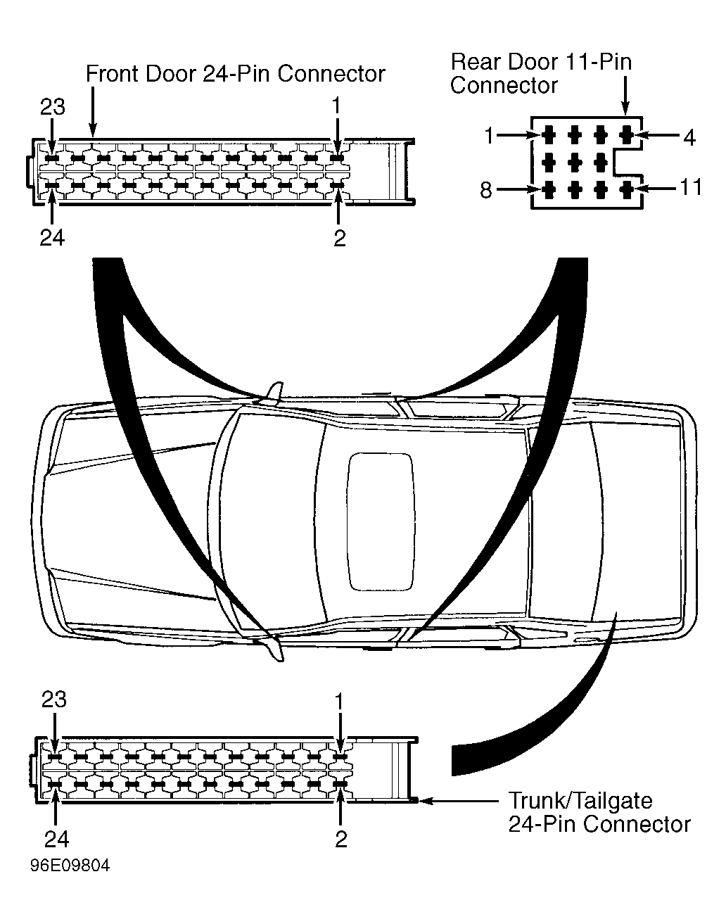
- Connect voltmeter between terminals No. 5 and 6 of driver's door 24-pin male connector, terminals No. 5 and 6 of passenger's door 24-pin male connector, terminals No. 1 and 2 of rear door 11-pin female connector, and terminals No. 11 and 12 of trunk/tailgate 24-pin male connector. See Fig 3
. If voltmeter reads about zero volts in each test, go to next step. If voltmeter does not read about zero volts in each test, go to step 27).
 Courtesy of VOLVO CARS OF NORTH AMERICA.
- Ensure ignition is off. Remove panels in door, luggage compartment, or trunk as necessary. Disconnect central locking module connector.
- Connect ohmmeter between terminals No. 5 and 6 of passenger door 24-pin connector, terminals No. 1 and 2 of rear door 11-pin connector, and terminals No. 11 and 12 of trunk/tailgate 24-pin connector. See Fig 3
. If ohmmeter reads about 1-15 ohms in each test, go to step 17). If ohmmeter does not read about 1-15 ohms in each test, go to next step.
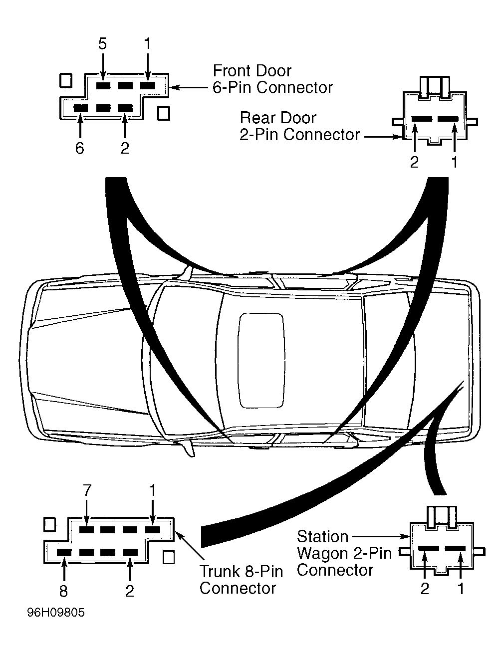
- Ensure ignition is off. Remove door panels from both front doors. Disconnect central locking module connector. Connect ohmmeter between front door 6-pin male connector terminals No. 4 and 5, between rear door 2-pin male connector terminals No. 1 and 2, between trunk 8-pin male connector terminals No. 6 and 7, and/or between station wagon 2-pin male connector terminals No. 1 and 2. See Fig 4
. Ohmmeter should read 1-15 ohms in each case. If all readings are okay, check wiring for an open circuit. If any reading is incorrect, check central locking module harness for an open or short circuit. Also check central locking unit where ohmmeter showed incorrect reading.
 Courtesy of VOLVO CARS OF NORTH AMERICA.
- Remove central locking relay and driver's door relay. Lock driver's door with key and keep key turned as far as it will go. Connect ohmmeter between central locking relay connector terminals No. 31 and LK. See Fig 2
. Ohmmeter should read about zero ohms. Connect ohmmeter between central locking relay connector terminals No. 31 and ULK. Ohmmeter should read infinite resistance.
- Unlock driver's door using key and keep key turned as far as it will go. Connect ohmmeter between central locking relay connector terminals No. 31 and LK. Ohmmeter should read infinite resistance. Connect ohmmeter between central locking relay connector terminals No. 31 and ULK. See Fig 2
. Ohmmeter should read about zero ohms. Repeat measurements for passenger's door. If any reading is incorrect, go to next step. If all readings are correct, go to step 24).
- Ensure ignition is off. Remove door panels from both front doors. Disconnect central locking module 6-pin connector. See Fig 4
. Lock driver's door using key and keep key turned as far as it w ill go. Connect ohmmeter between 6-pin connector terminals No. 1 and 2. Ohmmeter should read infinite resistance. Connect ohmmeter between 6-pin connector terminals No. 1 and 3. Ohmmeter should read about zero ohms.
- Unlock driver's door using key and keep key turned as far as it will go. Connect ohmmeter between 6-pin connector terminals No. 1 and 2. See Fig 4
. Ohmmeter should read about zero ohms. Connect ohmmeter between 6-pin connector terminals No. 1 and 3. Ohmmeter should read infinite resistance. Repeat measurements for passenger door. If all readings are correct, go to next step. If all readings are not correct, check for fault in central locking module switch or harness.
- Ensure ignition is off. Connect ohmmeter between driver's door central control module 6-pin connector terminal No. 1 and ground. See Fig 4
. Repeat measurement for passenger door. If about zero ohms are present, go to next step. If about zero ohms are not present, check for open or short circuit in ground wire.
- Turn ignition off. Ensure central locking module 6-pin connector is connected to front doors. See Fig 4
. Lock driver's door with key and keep key turned as far as it will go. Connect ohmmeter between central locking relay connector terminal No. 31 and LK. See Fig 2
. Ohmmeter should read about zero ohms.
- Unlock driver's door with key and keep key turned as far as it will go. Connect ohmmeter between central locking relay connector terminal No. 31 and LK. See Fig 2
. Ohmmeter should read infinite resistance.
- If readings are to specification, check for open or short circuit in unlocking signal lead between front door and central locking relay. If any reading is not to specification, check for open or short circuit in signal lead between front door and central locking relay. Go to next step.
- Ensure ignition is off. Remove central locking relay and driver's door relay. Connect voltmeter between driver's door relay connector terminals No. 31 and RD. See Fig 2
. Voltmeter should read zero volts. Connect ohmmeter between driver's door relay connector terminals No. 31 and RD. See Fig 2
. Ohmmeter should read infinite resistance. Connect ohmmeter between driver's door relay terminal RD and central locking relay terminal RD. Ohmmeter should read about zero ohms.
- If all readings are okay, go to next step. If all readings are not okay, check for open or short circuit in signal lead between terminal RD on central locking relay and terminal RD on driver's door relay.
- Turn ignition off. Ensure driver's door relay is installed. Disconnect central locking relay. Lock driver's door. Connect jumper wire between central locking relay connector terminals M- and No. 31. See Fig 2
. If driver's door central locking module switches to unlocked position, go to next step. If driver's door central locking module does not switch to unlocked position, replace driver's door relay.
- Ensure ignition is off. Remove central locking relay. Set passenger compartment dome light switch to position "O". Connect voltmeter between central locking relay connector terminals LA and No. 31. See Fig 2
. If voltmeter reads about zero volts, install new central locking relay. If voltmeter does not read about zero volts, check for short to voltage in interior lighting signal wiring between central locking relay connector terminal LA and dome light.