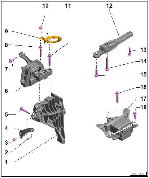
Overview - Assembly Mounts
 Courtesy of VOLKSWAGEN GROUP OF AMERICA, INC.
- Engine Support
- Bolt
- Replace after removing
- 10 Nm +90°
- Bolt
- Bracket
- Bolt
- Quantity: 3
- Replace after removing
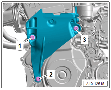
- Tightening specification and sequence. Refer to Fig 2.
- Engine Mount
- Bolt
- Replace after removing
- 25 Nm + 90°
- Bolt
- Engine mount to body
- Replace after removing
- 40 Nm +90°
- Ground Cable
- Depending on equipment/version
- Nut
- Depending on equipment/version
- Quantity: 2
- 9 Nm
- Bolt
- Engine mount to engine support
- Replace after removing
- 60 Nm +90°
- Pendulum Support
- Bolt
- Replace after removing
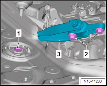
- Tightening specifications and sequence, M10 transmission bolts. Refer to Fig 3.
- Tightening specifications and sequence, M12 transmission bolts. Refer to Fig 4.
- Bolt
- Replace after removing
- Tightening specifications and sequence, M10 transmission bolts. Refer to Fig 3.
- Tightening specifications and sequence, M12 transmission bolts. Refer to Fig 4.
- Bolt
- Replace after removing
- Tightening specifications and sequence, M10 transmission bolts. Refer to Fig 3.
- Tightening specifications and sequence, M12 transmission bolts. Refer to Fig 4.
- Bolt
- Quantity: 3
- Replace after removing
- 60 Nm + 90°
- Transmission Mount
- Bolt
- Quantity: 4
- Replace after removing
- 50 Nm +90°
 Courtesy of VOLKSWAGEN GROUP OF AMERICA, INC.
| Step |
Bolts |
Tightening Specification/Additional Turn |
| 1. |
-1- through -3- |
7 Nm |
| 2. |
-1- through -3- |
40 Nm |
| 3. |
-1- through -3- |
90° |
 Courtesy of VOLKSWAGEN GROUP OF AMERICA, INC.
| Step |
Bolts |
Tightening Specification/Additional Turn |
| 1. |
-2- |
50 Nm |
| 2. |
-1- |
130 Nm |
| 3. |
-1- and -2- |
90° |
Courtesy of VOLKSWAGEN GROUP OF AMERICA, INC.
| Step |
Bolts |
Tightening Specification/Additional Turn |
| 1. |
-2- |
60 Nm |
| 2. |
-1- |
130 Nm |
| 3. |
-1- and -2- |
90° |