Intake Manifold: Removal: Removal
- DISCHARGE FUEL SYSTEM PRESSURE
. Refer to REMOVAL - Step 1
- DRAIN ENGINE COOLANT
. Refer to REPLACEMENT - Step 1
- REMOVE V-BANK COVER
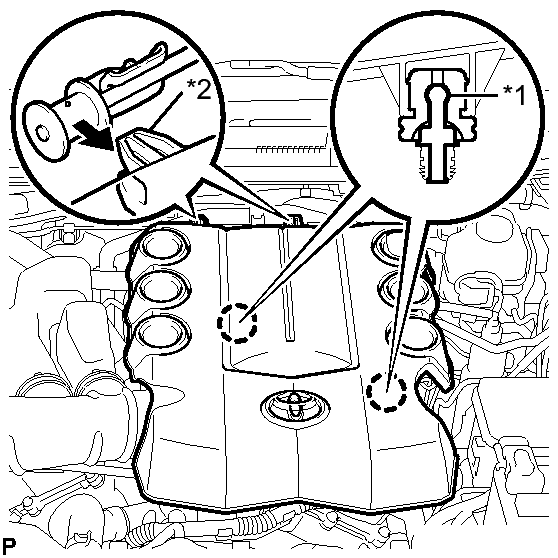
- Raise the front of the V-bank cover to disengage the 2 pins.
 Courtesy of © TOYOTA, LICENSE AGREEMENT TMS1002
- Remove the 2 V-bank cover hooks from the bracket.
- Remove the V-bank cover.
TEXT IN ILLUSTRATION
- REMOVE AIR CLEANER HOSE ASSEMBLY
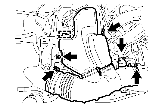
- Disconnect the ventilation hose and vacuum hose.
 Courtesy of © TOYOTA, LICENSE AGREEMENT TMS1002
- Disengage the wire harness clamp.
- Remove the bolt.
- Loosen the 2 hose clamps.
- Remove the air cleaner hose assembly.
- REMOVE INTAKE AIR SURGE TANK
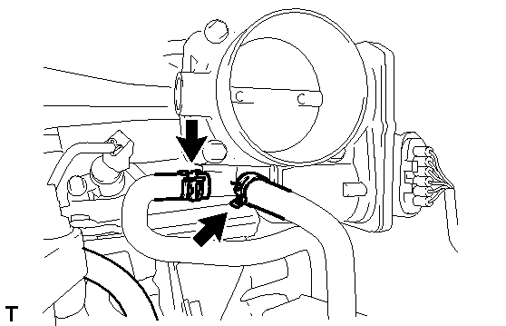
- Disconnect the No. 4 water by-pass hose.
 Courtesy of © TOYOTA, LICENSE AGREEMENT TMS1002
- Disconnect the No. 5 water by-pass hose.
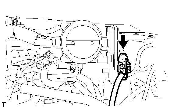
- Disconnect the throttle body connector.
 Courtesy of © TOYOTA, LICENSE AGREEMENT TMS1002
- Disconnect the No. 1 fuel vapor feed hose.
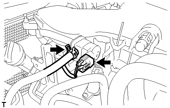 Courtesy of © TOYOTA, LICENSE AGREEMENT TMS1002
- Disconnect the No. 1 vacuum switching valve connector.
- Disconnect the No. 1 ventilation hose.
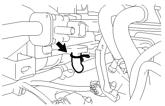 Courtesy of © TOYOTA, LICENSE AGREEMENT TMS1002
- Disconnect the 2 heater water hose clamps.
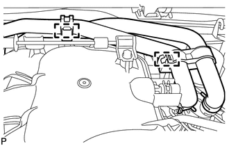 Courtesy of © TOYOTA, LICENSE AGREEMENT TMS1002
- Remove the 2 bolts and throttle body bracket.
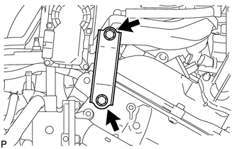 Courtesy of © TOYOTA, LICENSE AGREEMENT TMS1002
- Using a clip remover, disengage the wire harness clamp.
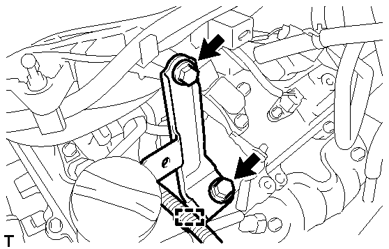 Courtesy of © TOYOTA, LICENSE AGREEMENT TMS1002
- Remove the 2 bolts and No. 1 surge tank stay.
- Remove the 2 bolts and No. 2 surge tank stay.
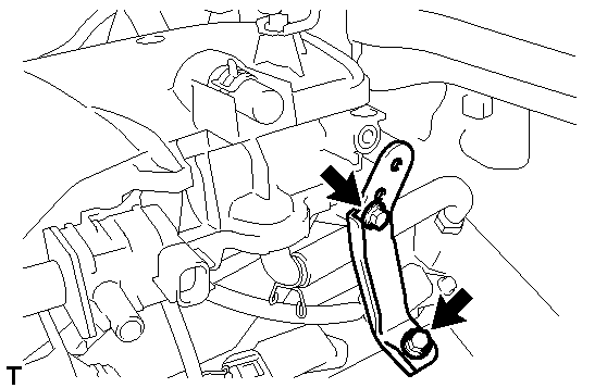 Courtesy of © TOYOTA, LICENSE AGREEMENT TMS1002
- Remove the 2 nuts.
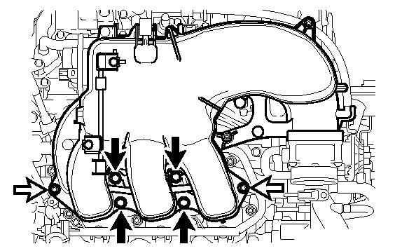 Courtesy of © TOYOTA, LICENSE AGREEMENT TMS1002
 TEXT IN ILLUSTRATION
 |
Nut |
- Using an 8 mm socket hexagon wrench, remove the 4 bolts and the intake air surge tank.
- Remove the gasket.
- REMOVE REAR CYLINDER HEAD COVER
. Refer to REMOVAL - Step 3
- DISCONNECT NO. 1 FUEL PIPE SUB-ASSEMBLY
. Refer to REMOVAL - Step 4
- DISCONNECT NO. 2 FUEL PIPE SUB-ASSEMBLY
. Refer to REMOVAL - Step 5
- REMOVE FUEL DELIVERY PIPE SUB-ASSEMBLY
. Refer to REMOVAL - Step 6
- REMOVE INTAKE MANIFOLD
- Remove the 4 nuts, 6 bolts and intake manifold.
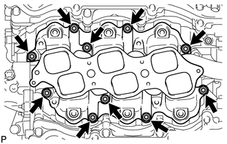 Courtesy of © TOYOTA, LICENSE AGREEMENT TMS1002
- Remove the 2 gaskets.