Test No. 1: Ignition Switch Does Not Operate In Each Position
- Check ignition switch. See IGNITION SWITCH under COMPONENT TESTS under STEERING COLUMN SWITCHES - CAMRY article in ACCESSORIES & EQUIPMENT. If ignition switch is okay, go to next step.
- Check power source for body control ECU by first checking the following fuses located in driver side junction block: ECU-ACC (5-amp), ECU-IG No. 2 (10-amp) and ECU-B (10-amp). Check DOOR No. 1 (25-amp) fuse located in engine compartment junction block. See BODY COMPUTER
in SYSTEM WIRING DIAGRAMS article. If all fuses are okay, go to next step. If any fuse is defective, replace fuse and repair wiring harness or electrical connector of affected circuit as necessary. After repairs have been made, perform confirmation test. See CONFIRMATION TEST under SELF-DIAGNOSTIC SYSTEM.
- Turn ignition off. Remove body control ECU from driver side junction block under left side of instrument panel. See Figure. DO NOT disconnect 22-pin electrical connector B6, 18-pin electrical connector B7, or 12-pin electrical connector B8 from side of body control ECU. The 24-pin driver side junction block-to-body control ECU connector is only accessible with body control ECU removed from junction block. See Fig 1.
- Turn ignition on. Using DVOM, check voltage with negative lead at ground circuit GND of 24-pin driver side junction block-to-body control ECU connector terminal No. 12 and positive lead at 24-pin driver side junction block-to-body control ECU connector terminals No. 1 (B), No. 2 (BDR1), No. 9 (SIG) and No. 10 (ACC). Perform same check with negative lead at ground circuit SGND of 24-pin driver side junction block-to-body control ECU connector terminal No. 24 and positive lead at 24-pin driver side junction block-to-body control ECU connector terminals No. 1 (B), No. 2 (BDR1), No. 9 (SIG) and No. 10 (ACC). See Fig 1. See BODY COMPUTER
in SYSTEM WIRING DIAGRAMS article. Voltage should be 10-14 volts at all test points. Go to next step.
- If all voltage readings are within specification, reinstall body control ECU and diagnosis by symptom. If any voltage reading is not within specification, check and repair ground circuits (GND and SGND) and electrical connectors between driver side junction block and ground points. See BODY COMPUTER
in SYSTEM WIRING DIAGRAMS article. If wiring harness and electrical connectors are okay, go to next step.
- Check and repair power circuits and electrical connectors between battery, ignition switch, driver side junction block and body control ECU. See BODY COMPUTER
in SYSTEM WIRING DIAGRAMS article. For additional wiring for power supply circuit, see POWER DISTRIBUTION
in SYSTEM WIRING DIAGRAMS article. Repair wiring harnesses or electrical connectors as necessary. After repairs have been made, perform confirmation test. See CONFIRMATION TEST under SELF-DIAGNOSTIC SYSTEM.
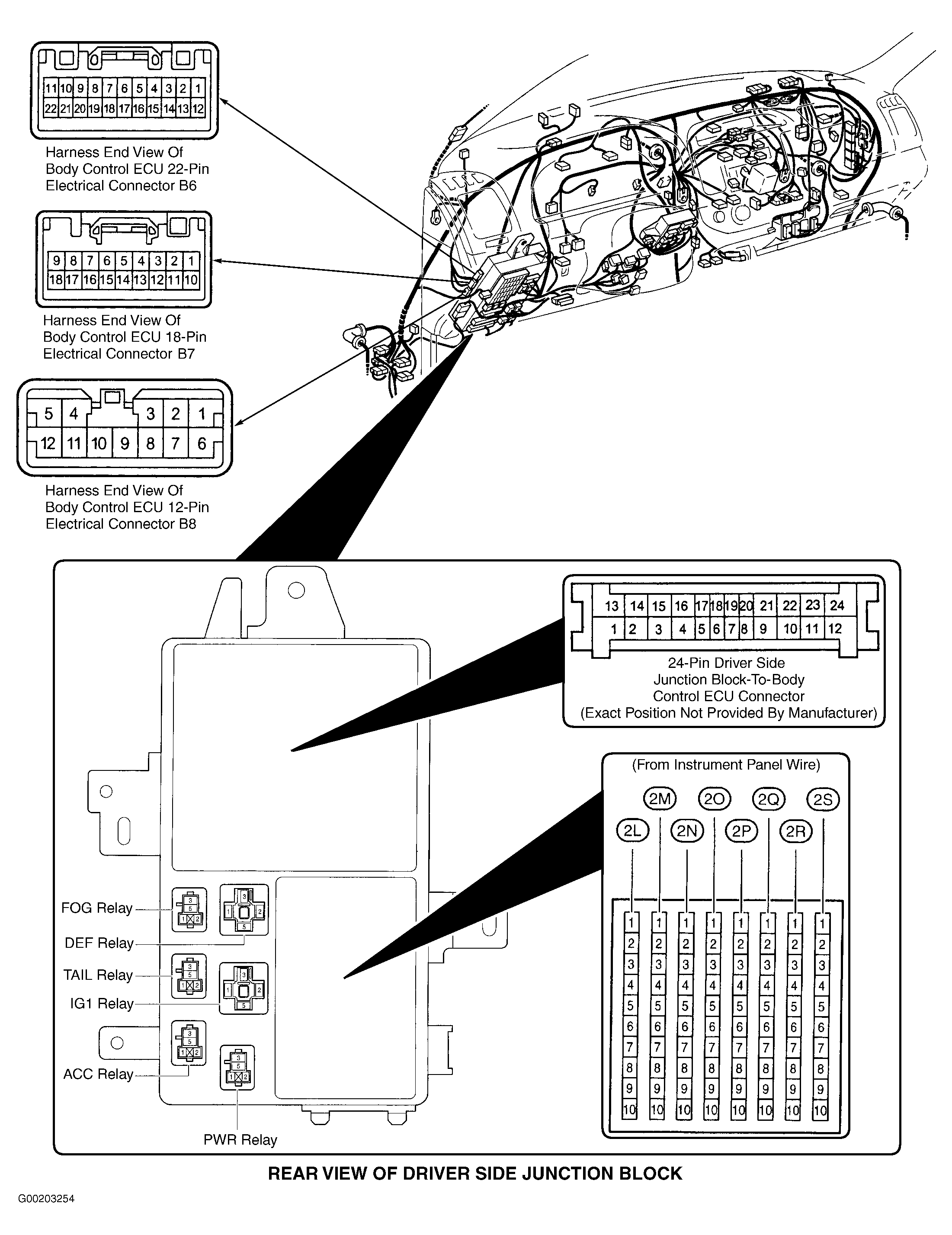 Courtesy of © TOYOTA, LICENSE AGREEMENT TMS1002