Transaxle Disassembly
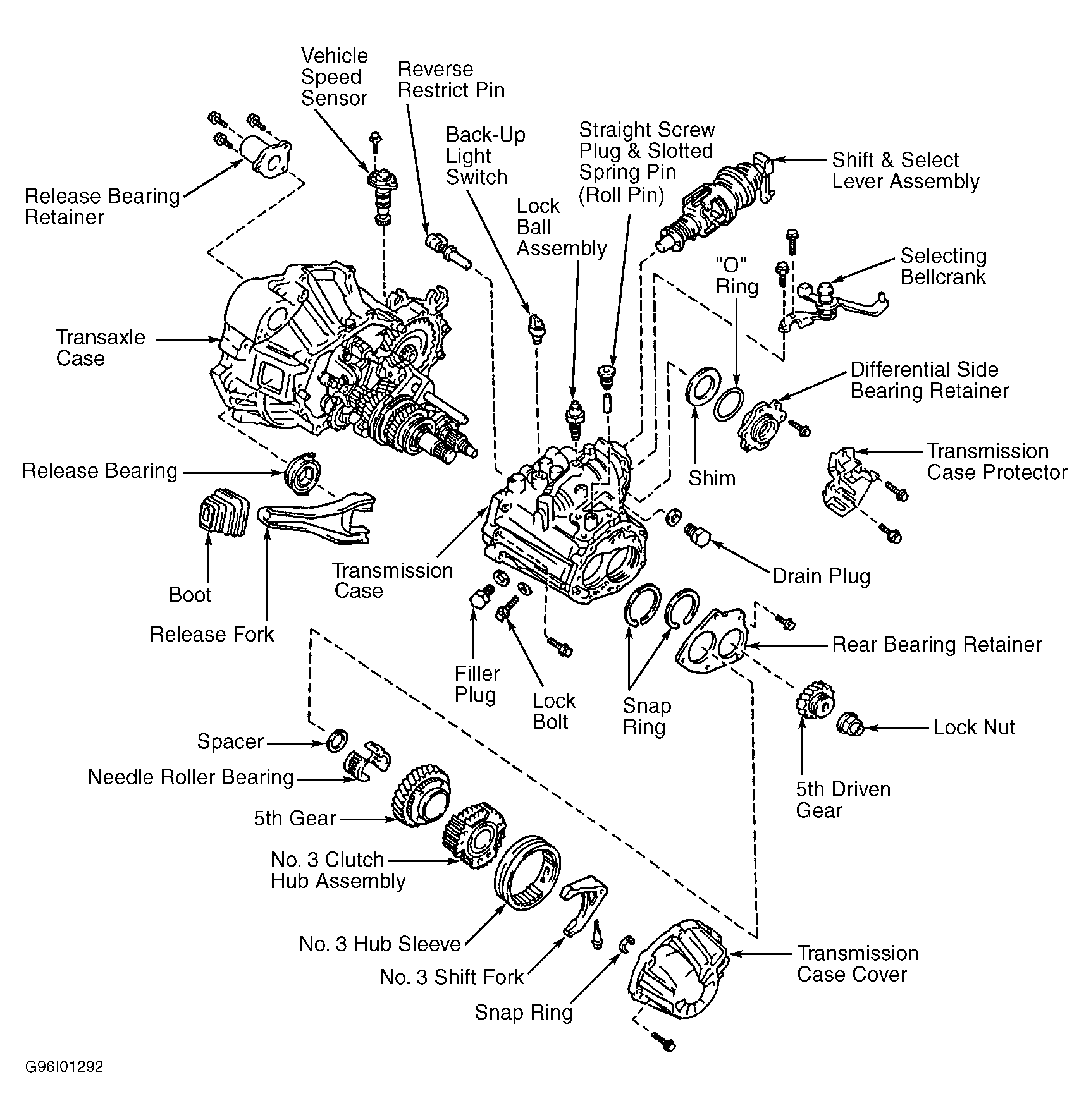
- Remove release fork and bearing. Remove vehicle speed sensor. Remove back-up light switch. Remove release bearing retainer. Remove engine mount bracket and selecting bellcrank. Remove transmission case cover. Remove lock ball assembly. Remove shift and select lever assembly. See Fig 1.
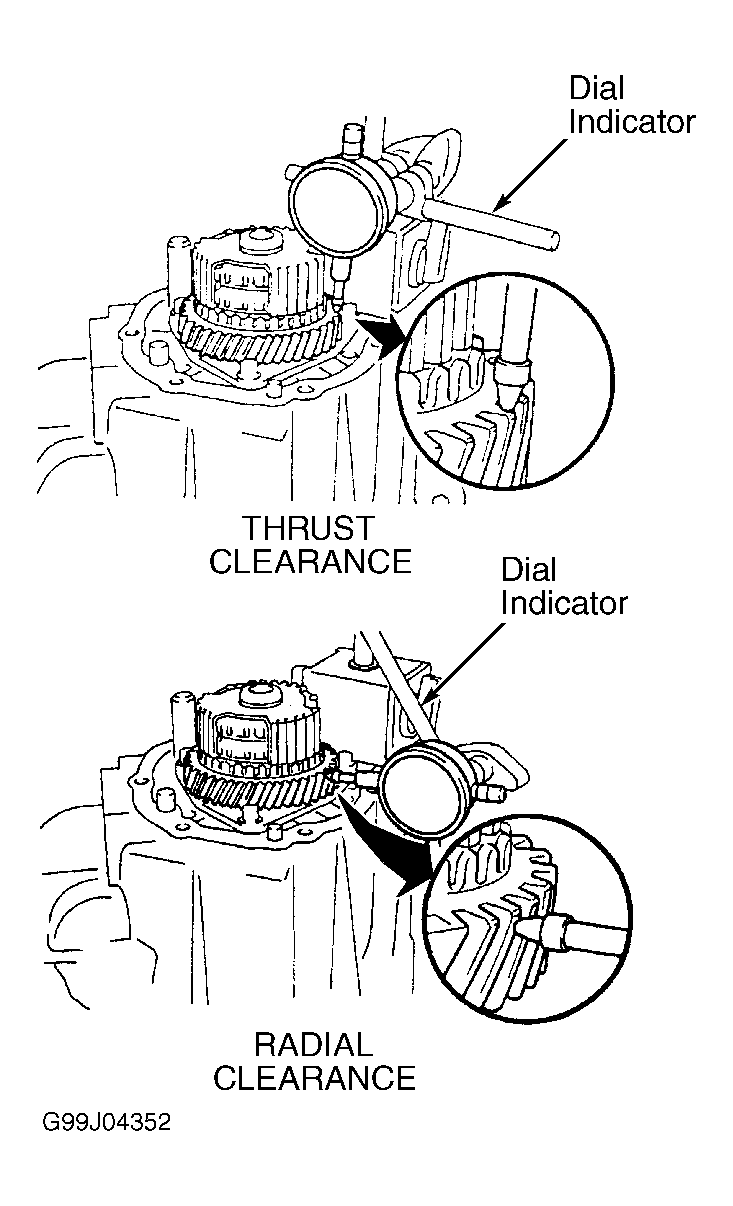
- Lock transmission in 2 gears. Using a hammer and chisel, lift staked section of output shaft lock nut. Remove lock nut. Lock nut has left-hand threads. Unlock transmission gears. Remove No. 3 shift fork set bolt, No. 3 hub sleeve and No. 3 shift fork. Remove 5th driven gear. Measure 5th gear clearance. See Fig 3. Using a dial indicator, measure and record thrust clearance. Standard clearance is .008-.016" (.20-.40 mm). Service limit is .018" (.45 mm). Measure radial clearance (oil clearance) of 5th gear. Standard clearance is .0004-.0020" (.009-.050 mm). Service limit is .0028" (.070 mm). If clearance exceeds maximum, replace gear, roller bearing or input shaft.
- Remove snap ring from output shaft. Using a puller, remove No. 3 clutch hub with synchronizer ring. Remove 5th gear. Remove needle roller bearing. Remove rear bearing retainer. Remove 2 bearing snap rings. Pull up on both shafts to assist removing snap rings.
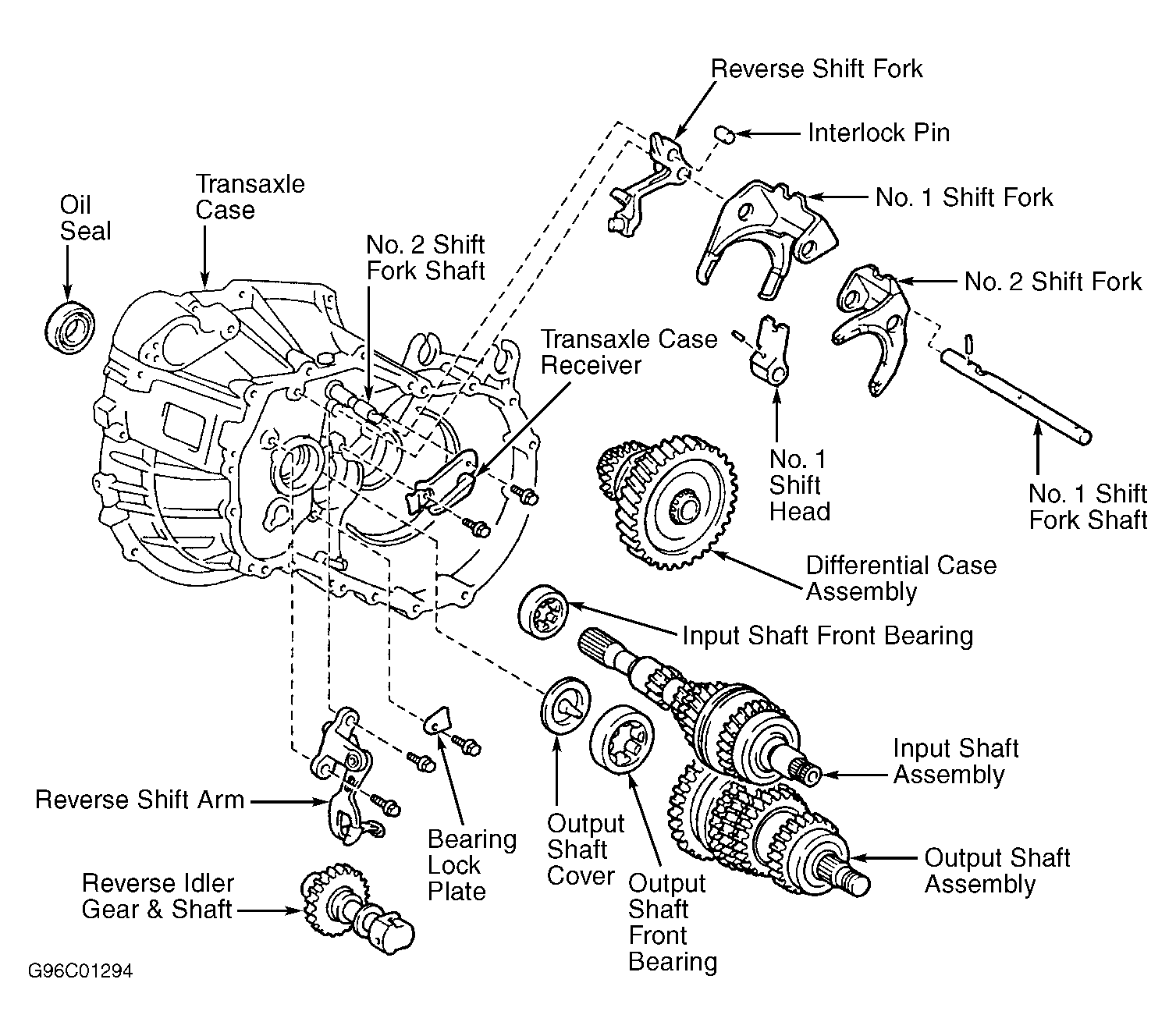
- Remove reverse idler gear shaft lock bolt and gasket. Remove differential side bearing retainer, "O" ring and shim. Remove transmission case. Remove reverse idler gear and shaft. Position No. 1 shift fork shaft in Reverse, remove bolts and pull off reverse shift arm. Shift fork shaft into Neutral. Remove screw plug and spring pin. Remove No. 2 shift fork shaft. Remove No. 1 shift fork shaft interlock pin. Remove No. 1 shift fork shaft, No. 1 shift head, No. 1 and No. 2 shift forks, reverse shift fork and input and output shaft assembly. See Fig 2.
- Mount shift rod and forks assembly in a vise. Using a pin punch and hammer, drive out 2 slotted spring pins from No. 1 shift fork shaft. Separate No. 1 shift fork shaft, No. 1 shift head, No. 1 and 2 shift forks and reverse shift fork. Remove differential assembly. Remove magnet from transaxle case. Remove No. 5 synchronizer ring with key spring from No. 3 clutch hub. Remove snap ring. Remove synchronizer rings.
- Remove transaxle case receiver. See Fig 2. Using Oil Seal Puller (09308-00010), remove input shaft front bearing. Using a press and Bearing Replacer (09310-35010), install a NEW input shaft front bearing. Install transaxle case receiver and tighten bolts to 65 INCH lbs. (7.3 N.m). Remove output shaft front bearing lock plate. Using Oil Seal Puller (09308-00010), remove output shaft front bearing. Remove bolt and bearing lock plate. See Fig 2. Using oil seal puller, remove output shaft front bearing. Using a press and bearing replacer, install NEW bearing. Install bearing lock plate and tighten bolt to 13 ft. lbs. (18 N.m). Replace input shaft seal.
- If necessary, replace reverse restrict pin. Remove straight screw plug. Using a pin punch and hammer, remove spring roll pin. Replace reverse restrict pin. Drive spring pin to a depth of .531" (13.5 mm). Apply sealant to plug threads, install and tighten to 9 ft. lbs. (12 N.m).
 Courtesy of © TOYOTA, LICENSE AGREEMENT TMS1002
 Courtesy of © TOYOTA, LICENSE AGREEMENT TMS1002
 Courtesy of © TOYOTA, LICENSE AGREEMENT TMS1002