Diagnostic Procedure
- If ABS warning light stays on, go tostep 4). If ABS warning light does not illuminate, check light bulb and replace as necessary. If bulb is okay, diagnose combination meter (instrument panel). See INSTRUMENT PANEL article in ACCESSORIES/SAFETY EQUIPMENT section.
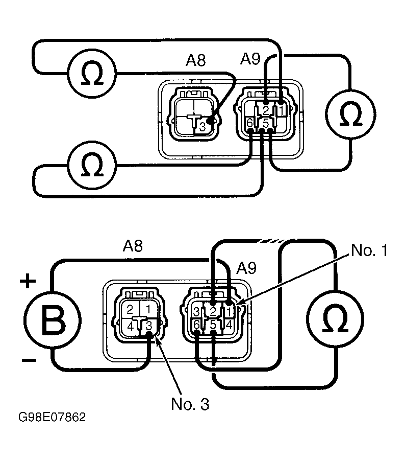
- Disconnect ABS relay connectors, located in engine compartment at front of vehicle. See Figure. Check continuity between specified ABS relay terminals. Continuity should exist between terminals No. 5 and 6 at solenoid relay (A9). Continuity should not exist between terminals No. 2 and 5 at solenoid relay (A9). Check resistance between motor relay (A8), terminal No. 3 and solenoid relay (A9), terminal No. 1. Resistance should be 80 ohms. Replace ABS solenoid relay if it does not test as described. See Fig 1.
- If relay tests as described, apply battery voltage between motor relay (A8), terminal No. 3 and solenoid relay (A9), terminal No. 1. Check continuity between terminals No. 2 and 5 at solenoid relay (A9). Continuity should exist. Check continuity between terminals No. 5 and 6 at solenoid relay (A9). Continuity should not exist. Check for continuity between terminals No. 4 and 5 at solenoid relay (A9). See Fig 1. If continuity does not exist, reverse test leads and recheck relay for continuity. If continuity does not exist, replace ABS solenoid relay. If continuity exists, check for open circuit in wiring harness between DLC1, ABS relay and ground. Repair as necessary. See WIRING DIAGRAMS .
- Retrieve DTCs. See RETRIEVING DTCS under DIAGNOSIS & TESTING . If DTC is present, perform appropriate test under DIAGNOSTIC TESTS . If DTC is not present, and ABS warning light is off when short pin is removed, go to next step. If ABS warning light does not turn off, check for short circuit in wiring harness between ABS warning light, DLC1 and ABS ECU. Repair as necessary. See WIRING DIAGRAMS .
- Check ABS relay. See steps 2) and 3) for test procedures. Replace relay as necessary. If relay is okay, check for short circuit in wiring harness between DLC1 and ABS relay. Repair as necessary. See WIRING DIAGRAMS .
 Courtesy of © TOYOTA, LICENSE AGREEMENT TMS1002