Test 1
- Circuit Fuse
- Turn ignition switch to OFF position. Ensure DOME fuse is okay. If DOME fuse is okay, go to next step. Replace fuse if necessary. If fuse fails again, check for short in circuit between fuse and Anti-Theft System (ATS) ECU connector "A" terminal No. 1 (Red wire). Repair short in harness or connectors as necessary.
- Power Source Circuit
- Turn ignition switch to OFF position and disconnect ATS ECU connectors. Ensure battery voltage exists between ECU connector "A" terminal No. 1 (Red wire) and ECU connector "B" terminal No. 4 (Black/White wire). If battery voltage exists, go to next step. If battery voltage does not exist, repair open in harness or connectors as necessary.
- Circuit Ground
- Ensure continuity exists between ground and ATS ECU connector "B" terminal No. 4 (White/Black wire). If continuity exists, go to next step. If continuity does not exist, repair open in harness or connectors or ground connection as necessary.
- Power Main Relay
- Turn ignition switch to OFF position. Remove power main relay from instrument panel junction block. Ensure continuity exists between relay terminals No. 1 and 2. See Fig 1. Continuity should not exist between relay terminals No. 3 and 5. Apply battery voltage between relay terminals No. 1 and 2. Continuity should exist between relay terminals No. 3 and 5 with battery voltage applied. If continuity is not as specified, replace relay. If continuity is as specified, check ATS ECU. See PIN VOLTAGE TESTS . If found to be defective, replace ATS ECU and retest system.
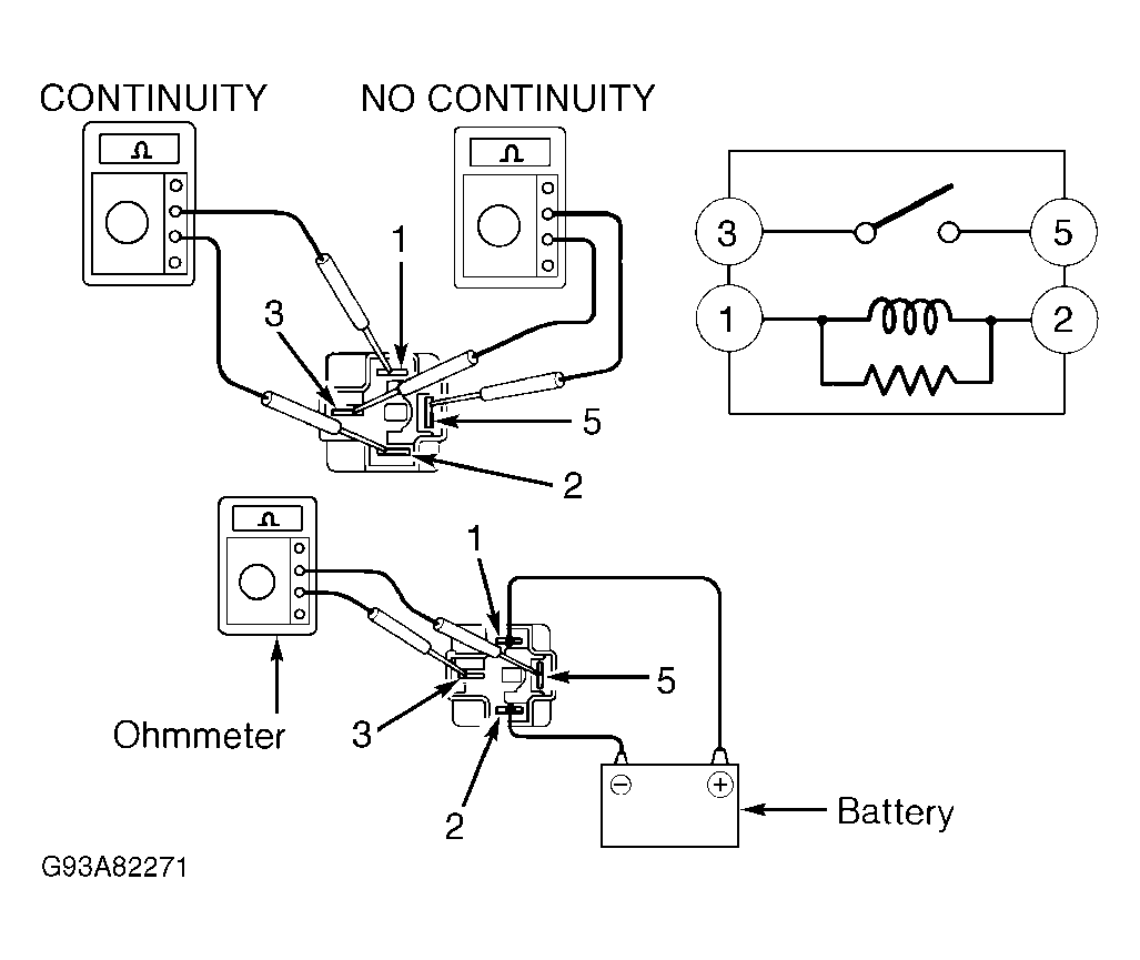 Courtesy of © TOYOTA, LICENSE AGREEMENT TMS1002