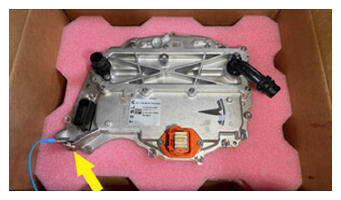
- Prepare the new rear drive unit inverter and attach the ESD strap to the new inverter housing
 Courtesy of TESLA, INC. Courtesy of TESLA, INC.
|
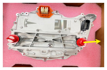
- Remove and discard the bolt that attaches the straight fluid coupling to the new front drive unit inverter, and then remove the coupling from the inverter.
 Courtesy of TESLA, INC. Courtesy of TESLA, INC.
|
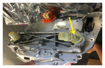
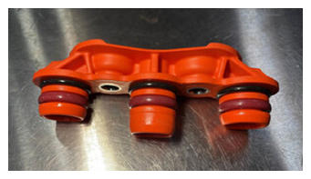
- Wet the 55 degrees fluid coupling O-ring with coolant, install the fluid coupling into the new front drive unit inverter, and then install a new bolt to attach the coupling to the inverter.
 6 N.m (4.4 ft-lbs)
 Courtesy of TESLA, INC. Courtesy of TESLA, INC.
|
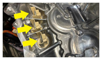
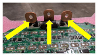
- Use an IPA wipe to clean the phase terminals of the front drive unit motor and the new front drive unit inverter, and allow at least one minute to dry.
 Courtesy of TESLA, INC. Courtesy of TESLA, INC.
|
 Courtesy of TESLA, INC. Courtesy of TESLA, INC.
|
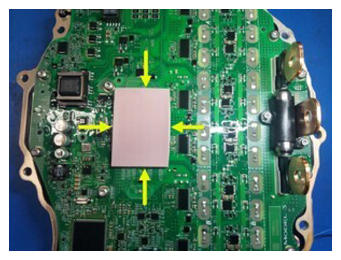
- Inspect the condition of the gap pad on the new front drive unit inverter PCB. Replace the gap pad if it does not fulfill these criteria:
- New and undamaged condition.
- Fully covers the discharge resistor array and no resistors are visible.
- Clean and free of debris.
- Evenly adhered to the inverter PCB.
 Courtesy of TESLA, INC. Courtesy of TESLA, INC.
|
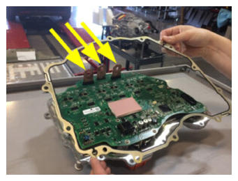
- Make sure that a new gasket is installed onto the new front drive unit inverter.
 Courtesy of TESLA, INC. Courtesy of TESLA, INC.
|
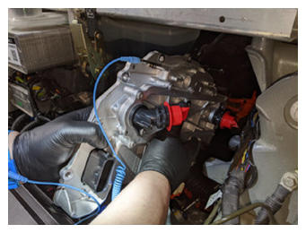
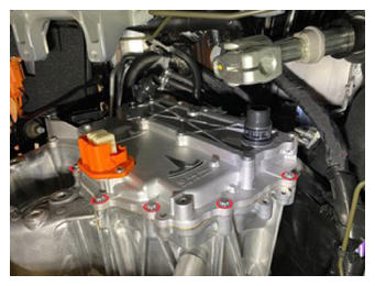
- Carefully move the front drive unit inverter down and in between the fan module and the multi-system beam. Align the inverter to the 2 pins in the front drive unit gearbox, and then install the inverter to the gearbox.
CAUTION:
Take care not to damage the inverter circuit board when installing the inverter.
NOTE:
Make sure that the phase terminals align during installation.
 Courtesy of TESLA, INC. Courtesy of TESLA, INC.
|
- Install and hand-tighten the bolts (x12) that attach the new front drive unit inverter to the front drive unit gearbox.
 Courtesy of TESLA, INC. Courtesy of TESLA, INC.
|
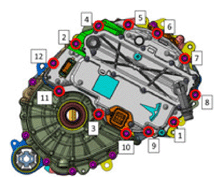
- Tighten the bolts (x12) that attach the new front drive unit inverter to the front drive unit gearbox in the sequence shown.
12.5 N.m (9.2 ft-lbs)
 Courtesy of TESLA, INC.
- Install and hand-tighten the bolts (x3) that attach the front drive unit motor 3-phase terminals to the new front drive unit inverter 3-phase terminals.
CAUTION:
If any bolts are dropped into the gearbox housing, they must be retrieved.
 Courtesy of TESLA, INC. Courtesy of TESLA, INC.
|
- Tighten the bolts (x3) that attach the front drive unit motor 3-phase terminals to the new front drive unit inverter 3-phase terminals.
11.5 N.m (8.5 ft-lbs)
NOTE:
If installing a new bolt, tighten to 12.5 N.m, back off 180 degrees, then torque to 5 N.m +40 degrees.
 Courtesy of TESLA, INC. Courtesy of TESLA, INC.
|
- Lightly lubricate the front drive unit gearbox phase out cover bores with EDF2 fluid, and if a new phase out cover is to be installed, lightly lubricate the O-rings of the cover.
 Courtesy of TESLA, INC. Courtesy of TESLA, INC.
|
- Install the phase out cover into the front drive unit gearbox, and then install the bolts (x2) that attach the cover to the gearbox.
14 N.m (10.3 ft-lbs)
 Courtesy of TESLA, INC. Courtesy of TESLA, INC.
|
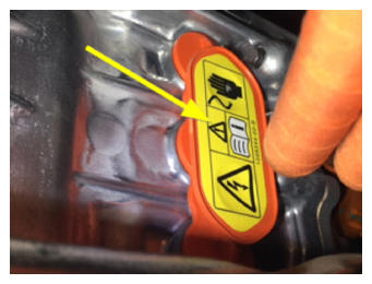
- Install a new phase out cover label.
 Courtesy of TESLA, INC. Courtesy of TESLA, INC.
|
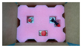
- Remove the ESD wrist strap from the new inverter, attach it to the old inverter, and prepare the old inverter for shipment to MRB.
 Courtesy of TESLA, INC. Courtesy of TESLA, INC.
|
- Remove ESD wrist strap.
 Courtesy of TESLA, INC. Courtesy of TESLA, INC.
|
- Perform an inverter air leak test. See Inverter Air Leak Test (In Vehicle)
.
- Install the front drive unit inverter cover to the front drive unit inverter, and then install the brush clips (x2) that attach the cover to the inverter.
 Courtesy of TESLA, INC. Courtesy of TESLA, INC.
|
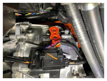
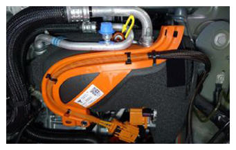
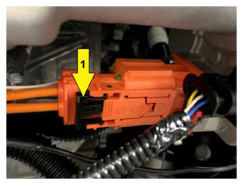
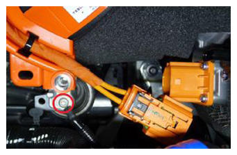
- Verify that the black release lever of the front drive unit HV harness connector is in the open position, install the connector flat and square to the front drive unit inverter HV header, secure the release lever to the closed position, and then slide the red connector locking tab.
 Courtesy of TESLA, INC. Courtesy of TESLA, INC.
|
 Courtesy of TESLA, INC. Courtesy of TESLA, INC.
|
- Install the bolt that attaches the front drive unit HV harness bracket to the front drive unit inverter.
10 N.m (7.4 ft-lbs)
 Courtesy of TESLA, INC. Courtesy of TESLA, INC.
|
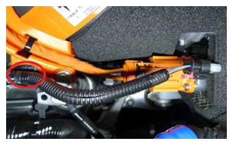
- Fasten the clip that attaches the front subframe electrical harness to the front drive unit inverter.
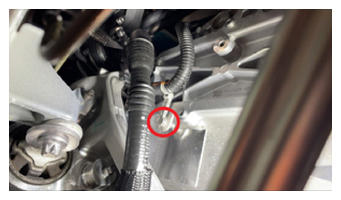 Courtesy of TESLA, INC. Courtesy of TESLA, INC.
|
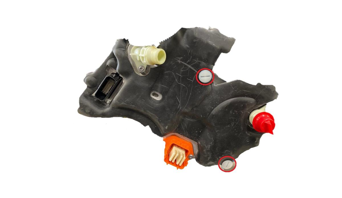
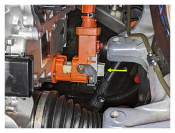
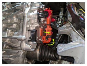
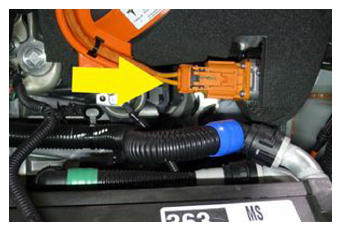
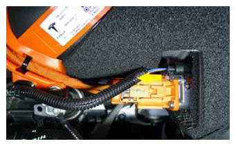
- Connect the front subframe electrical harness to the front drive unit inverter logic connector, raise the handle upward, and fasten the locking tab.
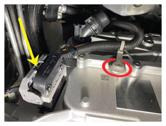 Courtesy of TESLA, INC. Courtesy of TESLA, INC.
|
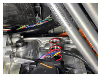
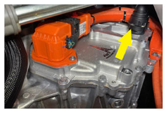
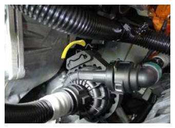
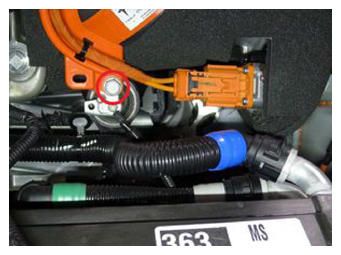
- Fasten the fir tree clip that attaches the front drive unit inverter inlet hose to the front drive unit inverter.
- Remove the plugs from the fittings, immediately connect the front drive unit inverter inlet hose to the front drive unit inverter, fasten the clip, and then perform a Push-Pull-Push check of the fitting.
 Courtesy of TESLA, INC. Courtesy of TESLA, INC.
|
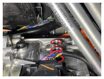
- Remove the plugs from the fittings, immediately connect the front drive unit inverter to heat exchanger hose to the front drive unit inverter outlet, fasten the clip, and then perform a Push-Pull-Push check of the fitting.
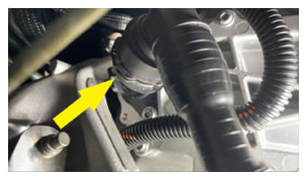 Courtesy of TESLA, INC. Courtesy of TESLA, INC.
|
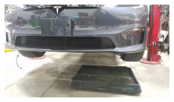
- Move the coolant catcher out from under the vehicle.
 Courtesy of TESLA, INC. Courtesy of TESLA, INC.
|
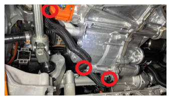
- Install the LH isolator mount to the front drive unit, install and hand-tighten the bolts (x3) that attach the isolator mount to the drive unit.
 Courtesy of TESLA, INC. Courtesy of TESLA, INC.
|
 Courtesy of TESLA, INC. Courtesy of TESLA, INC.
|
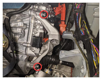
- Tighten the front side bolts (x2) that attach the isolator mount to the drive unit.
35 N.m (25.8 ft-lbs) +55 deg
NOTE:
The third bolt is torqued in a later step.
 Courtesy of TESLA, INC. Courtesy of TESLA, INC.
|
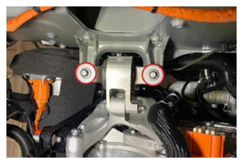
- Install the LH clevis mount to the LH isolator mount, and then install and hand-tighten the bolts (x2) that attach the clevis mount to the isolator mount.
 Courtesy of TESLA, INC. Courtesy of TESLA, INC.
|
- Install and hand-tighten the bolts (x2) that attach the LH clevis mount to the LH frame rail.
NOTE:
Use a pry bar between the steering rack and front drive unit to help with bolt installation.
 Courtesy of TESLA, INC. Courtesy of TESLA, INC.
|
 Courtesy of TESLA, INC. Courtesy of TESLA, INC.
|
 Courtesy of TESLA, INC. Courtesy of TESLA, INC.
|
- Tighten the forward bolt that attaches the clevis mount to the frame rail.
65 N.m (47.9 ft-lbs)
NOTE:
The rearward bolt is tightened in a later step.
 Courtesy of TESLA, INC. Courtesy of TESLA, INC.
|
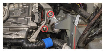
- Tighten the bolts (x2) that attach the LH clevis mount to the LH isolator mount.
62 N.m (45.7 ft-lbs)
 Courtesy of TESLA, INC. Courtesy of TESLA, INC.
|
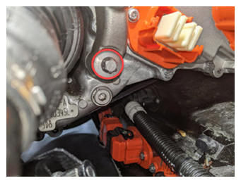
- Tighten the rear bolt that attaches the LH isolator mount to the front drive unit.
35 N.m (25.8 ft-lbs) +55 deg
 Courtesy of TESLA, INC. Courtesy of TESLA, INC.
|
- Tighten the rearward bolt that attaches the LH clevis mount to the LH frame rail.
65 N.m (47.9 ft-lbs)
 Courtesy of TESLA, INC. Courtesy of TESLA, INC.
|
- Fasten the clips (x4) that attach the front drive unit inverter to heat exchanger hose to the front drive unit.
 Courtesy of TESLA, INC. Courtesy of TESLA, INC.
|
 Courtesy of TESLA, INC. Courtesy of TESLA, INC.
|
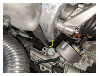
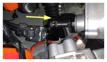
- Slide the steering column intermediate shaft down and onto the steering rack input shaft.
 Courtesy of TESLA, INC. Courtesy of TESLA, INC.
|
- Install the bolt that attaches the steering column intermediate shaft to the steering rack input shaft.
30 N.m (22.1 ft-lbs)
 Courtesy of TESLA, INC. Courtesy of TESLA, INC.
|
- Install the front skid plate. See Skidplate - Front (Remove and Replace)
.
- Install the front aero shield panel. See Panel - Aero Shield - Front (Remove and Replace)
.
- Install the mid aero shield panel. See Panel - Aero Shield - Mid (Remove and Replace)
.
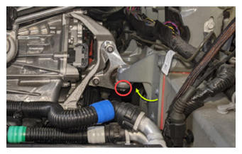
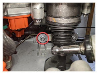
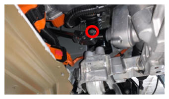
- Install the front drive unit ground strap to the front drive unit, and then install the bolt that attaches the ground strap to the drive unit.
6 N.m (4.4 ft-lbs)
 Courtesy of TESLA, INC. Courtesy of TESLA, INC.
|
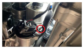
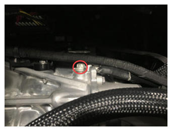
- Install the front drive unit ground strap to the LH body casting, and then install the bolt that attaches the ground strap to the body casting.
15 N.m (11.1 ft-lbs)
 Courtesy of TESLA, INC. Courtesy of TESLA, INC.
|
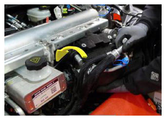
- Install new O-rings onto the Supermanifold to HVAC lines, and wet the O-rings with refrigerant oil.
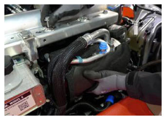
- Move the Supermanifold to HVAC lines in and around the coolant reservoir.
 Courtesy of TESLA, INC. Courtesy of TESLA, INC.
|
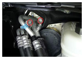
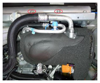
- Install the Supermanifold to HVAC lines to the HVAC assembly, and then install the bolts (x2) that attach the lines to the HVAC assembly.
22 N.m (16.2 ft-lbs)
 Courtesy of TESLA, INC. Courtesy of TESLA, INC.
|
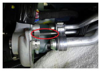
- Place a clean shop towel under the Supermanifold plate, and then install the Supermanifold to HVAC lines into the Supermanifold plate.
NOTE:
Move the lines rearward so that the stud clears the Supermanifold plate, then insert the lines into the plate.
 Courtesy of TESLA, INC. Courtesy of TESLA, INC.
|
 Courtesy of TESLA, INC. Courtesy of TESLA, INC.
|
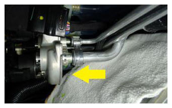
- Install the nut that attaches the Supermanifold to HVAC line to the Supermanifold plate.
27 N.m (19.9 ft-lbs)
 Courtesy of TESLA, INC. Courtesy of TESLA, INC.
|
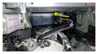
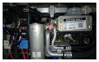
- With the help of an assistant, install the A/C compressor in under the multi-system beam, and then install and hand-tighten the bolts (x2) that attach the A/C compressor bracket to the multi-system beam.
 Courtesy of TESLA, INC. Courtesy of TESLA, INC.
|
 Courtesy of TESLA, INC. Courtesy of TESLA, INC.
|
- Tighten the bolts (x2) that attach the A/C compressor bracket to the multi-system beam.
31 N.m (22.9 ft-lbs)
 Courtesy of TESLA, INC. Courtesy of TESLA, INC.
|
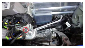
- Install the Supermanifold to A/C compressor lines to the Supermanifold, and then install the bolt that attaches the lines to the Supermanifold.
22 N.m (16.2 ft-lbs)
 Courtesy of TESLA, INC. Courtesy of TESLA, INC.
|
- Perform the A/C vacuum and run leak test. See A/C Refrigerant (Recovery and Recharge)
.
NOTE:
Perform the next steps concurrent with A/C vacuum and run leak test.
- Slide the powertrain coolant pump onto the A/C compressor lower bracket toward the A/C compressor.
 Courtesy of TESLA, INC. Courtesy of TESLA, INC.
|
- Fasten the clip that attaches the coolant hose to the A/C compressor bracket.
 Courtesy of TESLA, INC. Courtesy of TESLA, INC.
|
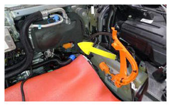
- Move the HV heat pump bracket in to under the A/C compressor discharge pipe.
 Courtesy of TESLA, INC. Courtesy of TESLA, INC.
|
 Courtesy of TESLA, INC. Courtesy of TESLA, INC.
|
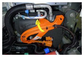
- Rotate the HV heat pump bracket rearward and down to hook the bracket onto the A/C compressor eyelet, and then rotate the HV heat pump bracket down and against the A/C compressor.
 Courtesy of TESLA, INC. Courtesy of TESLA, INC.
|
- Connect the HV harness from the A/C compressor HV header, and then slide the black locking tab.
 Courtesy of TESLA, INC. Courtesy of TESLA, INC.
|
 Courtesy of TESLA, INC. Courtesy of TESLA, INC.
|
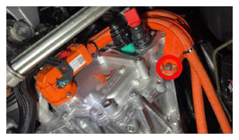
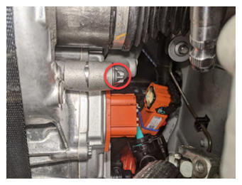
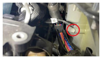
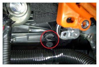
- Install the bolt that attaches the A/C compressor HV harness bracket to the A/C compressor.
9 N.m (6.6 ft-lbs)
 Courtesy of TESLA, INC. Courtesy of TESLA, INC.
|
- Install the ground strap to the A/C compressor, and then install the bolt that attaches the ground strap to the compressor.
7 N.m (5.2 ft-lbs)
 Courtesy of TESLA, INC. Courtesy of TESLA, INC.
|
- Fasten the clip that attaches the electrical harness to the A/C compressor HV harness bracket.
 Courtesy of TESLA, INC. Courtesy of TESLA, INC.
|
- Connect the electrical harness to the A/C compressor logic connector, and then push the red tab to secure the connector.
 Courtesy of TESLA, INC. Courtesy of TESLA, INC.
|
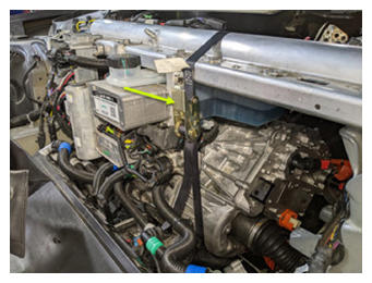
- Remove the ratchet strap supporting the LH side of the front drive unit from the multi-system beam.
 Courtesy of TESLA, INC. Courtesy of TESLA, INC.
|
- Recharge the A/C refrigerant. See A/C Refrigerant (Recovery and Recharge)
.
NOTE:
Perform the next steps concurrent with A/C refrigerant recharge.
- Install the underhood storage unit. See Underhood Storage Unit (Remove and Replace)
.
NOTE:
Do not install the rear underhood apron at this time.
- Perform a cooling system vacuum refill. See Cooling System (Vacuum Refill)
.
- When the A/C refrigerant recharge completes, disconnect the A/C machine from the vehicle. See A/C Refrigerant (Recovery and Recharge)
.
- Connect LV power. See LV Power (Disconnect and Connect)
.
- Connect the LV maintainer and disconnect the LV battery. See LV Maintainer (Connect and Disconnect)
.
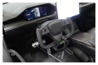
- Remove the steering wheel lock and remove the protector sheet from the driver seat.
 Courtesy of TESLA, INC. Courtesy of TESLA, INC.
|
- If necessary, enable Service Mode, unlock the gateway, and enable Service Mode Plus. See Service Mode (Enable and Disable)
, Gateway (Unlock)
, and Service Mode Plus
.
- If necessary, on the touchscreen, touch High Voltage Procedures
, and under Drive-Inverter-Replacement, touch Front Drive Inverter Replacement
.
- On the touchscreen, under After Inverter Replacement, touch Stop Fluid Fill/Drain
, touch Run
, allow the routine to complete, and then touch Close
.
- Under After Inverter Replacement, touch Restore Bootloader Data,
press and release the brake pedal, touch Run,
allow the routine to complete, and then touch Close.
- Under After Inverter Replacement, touch CAN Redeploy,
touch Run,
allow the routine to complete, and then touch Close
.
- Connect the LV battery and disconnect the LV maintainer. See LV Maintainer (Connect and Disconnect)
.
- Under After Successful Redeploy, touch Restore Application Data,
press and release the brake pedal, touch Run,
allow the routine to complete, and then touch Close.
- Under After Inverter Replacement, touch Heatpump Commissioning,
touch Run,
allow the routine to complete, and then touch Close.
- Under After Successful Redeploy, touch Coolant Air Purge,
touch Run,
allow the routine to complete, and then touch Close
.
- Under After Successful Redeploy, touch Thermal System Test,
touch Run,
allow the routine to complete, and then touch Close.
- Add coolant to the reservoir as necessary.
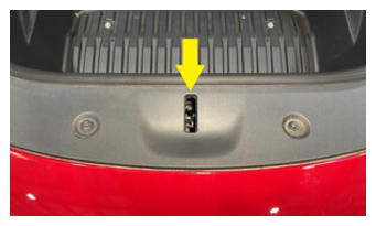
- Manually engage the hood latch.
NOTE:
If the hood is open, or if the hood latch is not manually engaged, the vehicle speed will be limited and the resolver learn routine will fail.
 Courtesy of TESLA, INC. Courtesy of TESLA, INC.
|
- Under After Successful Redeploy, touch Resolver Error Learn,
read the instructions displayed, touch Run,
follow the instructions, allow the routine to complete, and then touch Close.
- Install the LH and RH front wheels. See Wheel (Remove and Install)
.
- On the vehicle touchscreen, open the hood to disengage the hood latch.
- Install the rear underhood apron. See Underhood Apron - Rear (Remove and Replace)
.
- Disable Service Mode Plus. See Service Mode Plus
.
- Disable Service Mode. See Service Mode (Enable and Disable)
.
- Disconnect the laptop with Toolbox 3 from the vehicle. See Toolbox 3 (Connect and Disconnect)
.
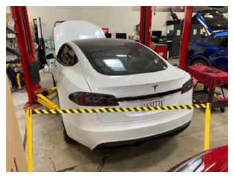
- Remove the stanchions from around the rear of vehicle.
 Courtesy of TESLA, INC. Courtesy of TESLA, INC.
|
- Remove the vehicle from the 2 post lift. See Raise Vehicle - 2 Post Lift
.