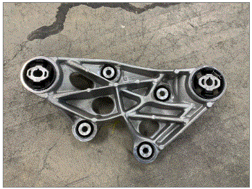
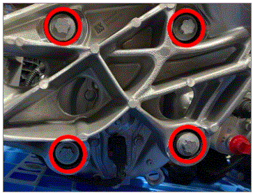
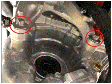
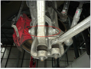
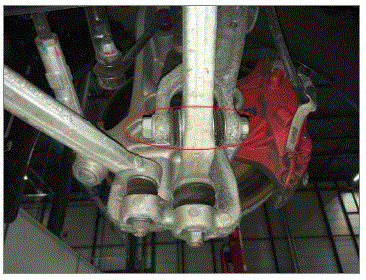
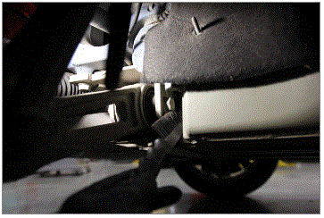
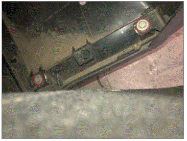
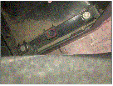
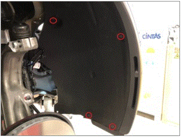
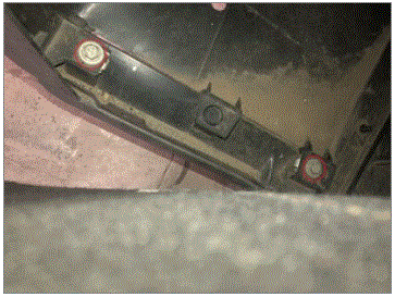
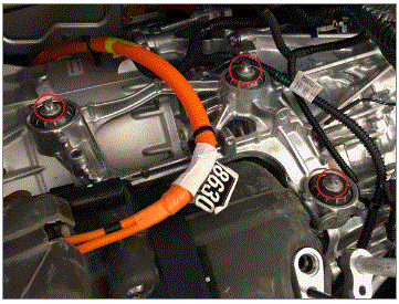
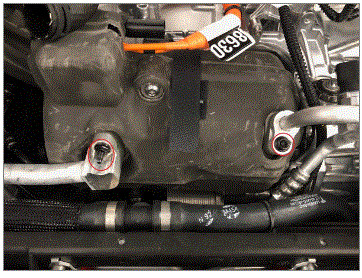
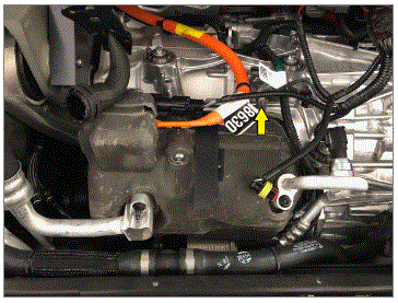
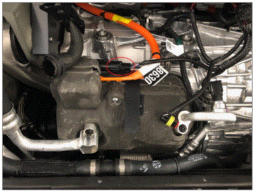
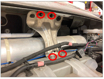
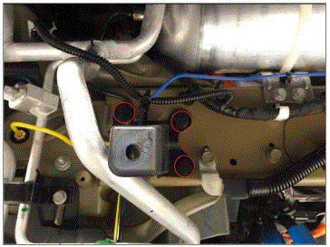
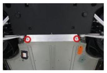
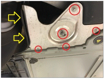
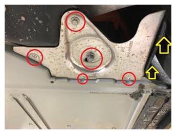
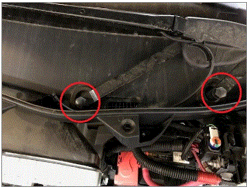
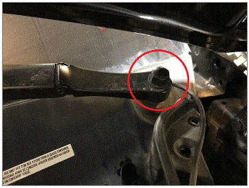
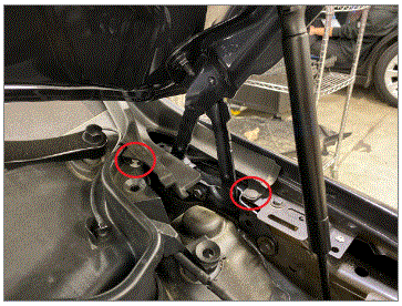
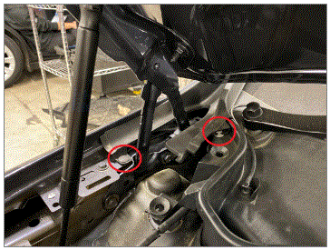
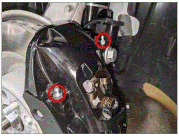
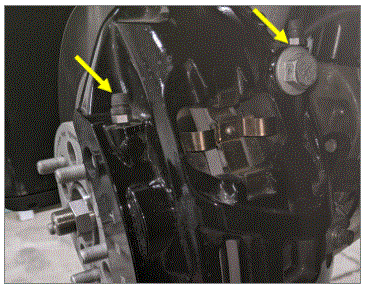
- Secure bushing carrier assembly to FDU
NOTE:
4x bolts, EP20, 60 N.m +50 degrees, Torque sequence - Bottom right, top left, bottom left, top right
 Courtesy of TESLA, INC. Courtesy of TESLA, INC.
|
 Courtesy of TESLA, INC. Courtesy of TESLA, INC.
|
 Courtesy of TESLA, INC. Courtesy of TESLA, INC.
|
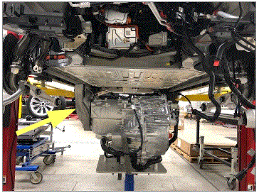
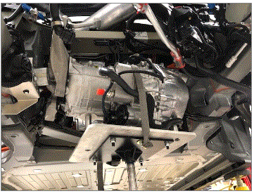
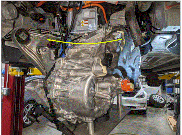
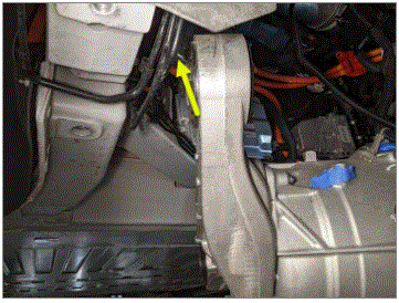
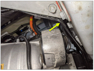
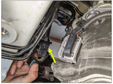
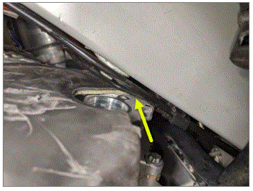
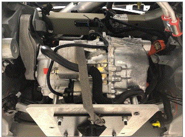
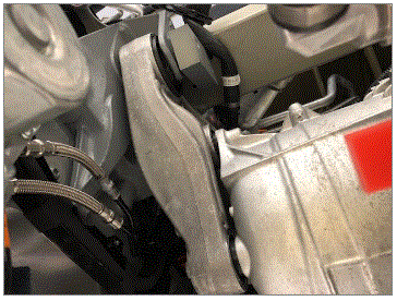
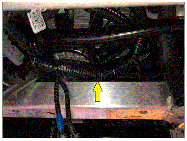
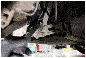
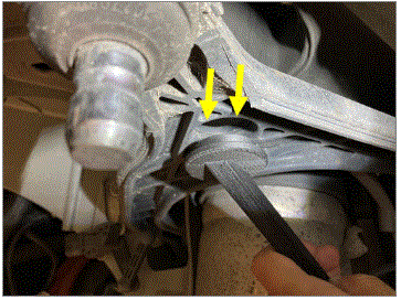
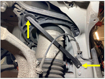
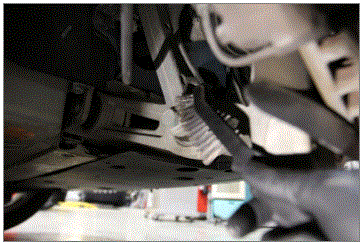
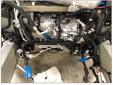
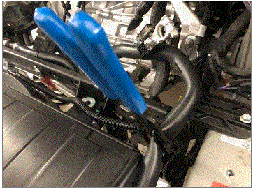
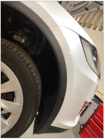
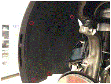
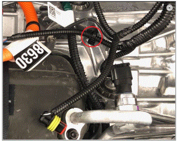
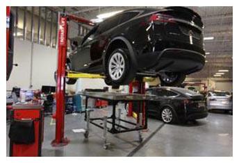
- Install the FDU into the vehicle
NOTE:
The FDU will need to be manipulated in such a way to clear the front 4 tube break bundle, AC suction line and body, Be extremely cautious to avoid damage to surrounding components.
 Courtesy of TESLA, INC. Courtesy of TESLA, INC.
|
 Courtesy of TESLA, INC. Courtesy of TESLA, INC.
|
 Courtesy of TESLA, INC. Courtesy of TESLA, INC.
|
 Courtesy of TESLA, INC. Courtesy of TESLA, INC.
|
 Courtesy of TESLA, INC. Courtesy of TESLA, INC.
|
 Courtesy of TESLA, INC. Courtesy of TESLA, INC.
|
 Courtesy of TESLA, INC. Courtesy of TESLA, INC.
|
 Courtesy of TESLA, INC. Courtesy of TESLA, INC.
|
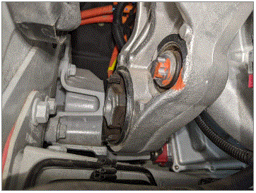
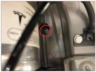
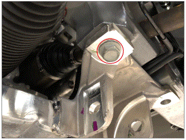
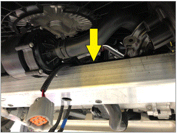
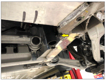
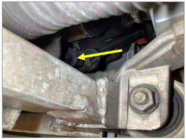
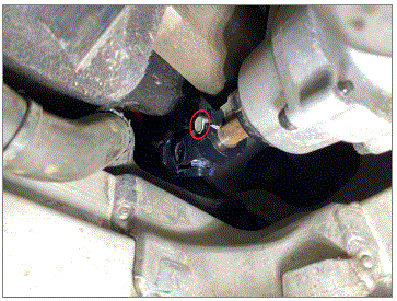
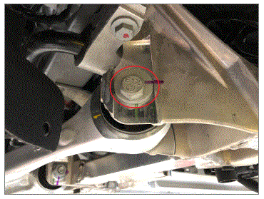
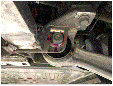
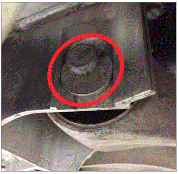
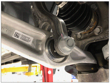
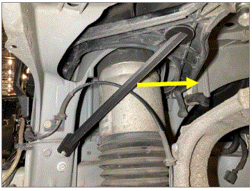
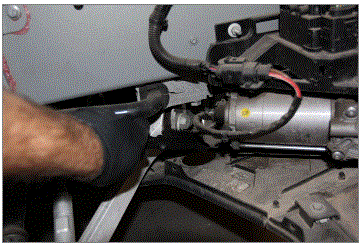
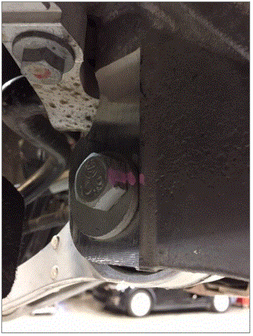
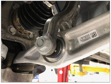
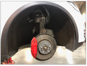
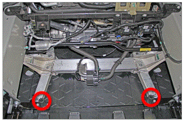
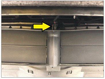
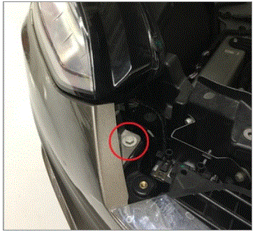
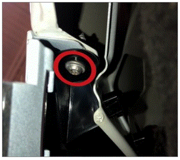
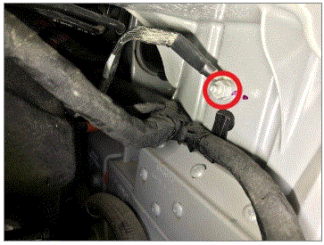
- Install the rear lower bolt securing the RH FDU mount to the body
NOTE:
1x bolt, E20, 120 N.m
 Courtesy of TESLA, INC. Courtesy of TESLA, INC.
|
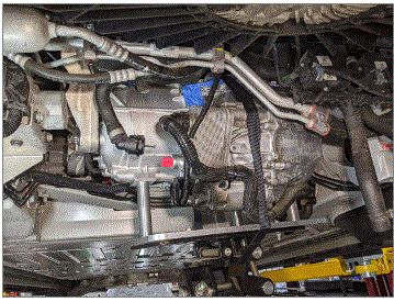
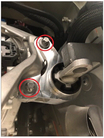
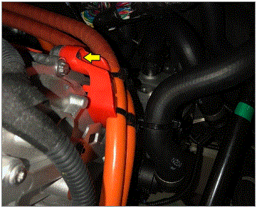
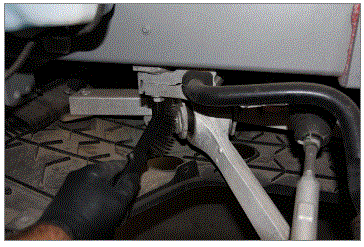
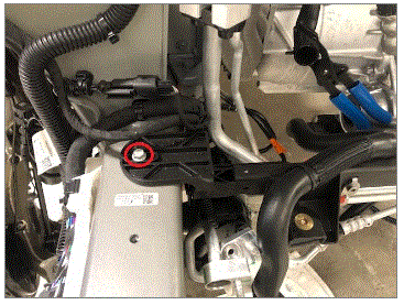
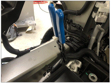
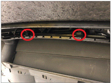
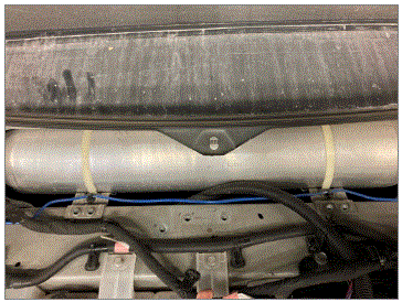
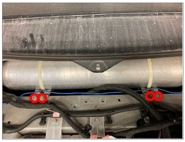
- Position the isolator mount in position and install the bolts securing the isolator mount to the FDU
NOTE:
2x bolts, E14, 38 N.m
 Courtesy of TESLA, INC. Courtesy of TESLA, INC.
|
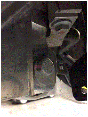
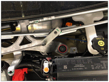
- Position the clevis mount to the isolator mount and install the bolts securing the clevis mount to the isolator mount
NOTE:
2x bolts, E14, 92 N.m
 Courtesy of TESLA, INC. Courtesy of TESLA, INC.
|
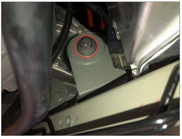
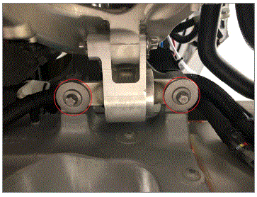
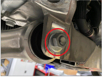
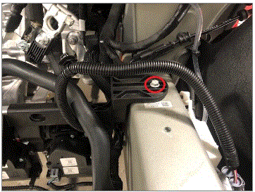
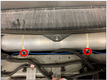
- Install the bolts securing the clevis mount to the body
NOTE:
2x bolts, E14, 65 N.m, Ensure the mount is positioned all the way forward before torquing, Allowing the mount to be installed all the way rearward will result in NVH issues
 Courtesy of TESLA, INC. Courtesy of TESLA, INC.
|
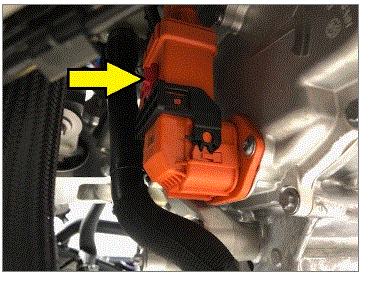
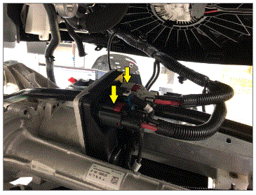
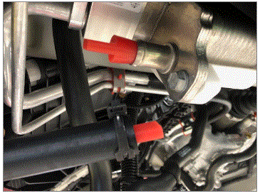
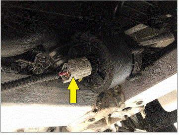
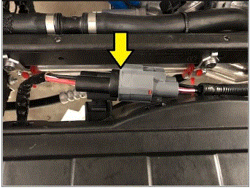
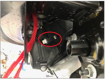
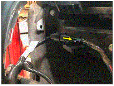
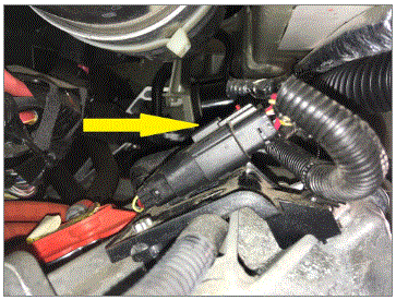
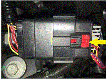
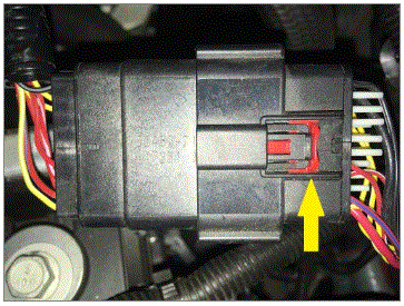
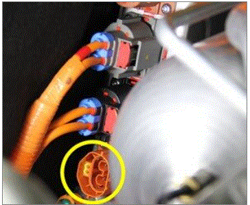
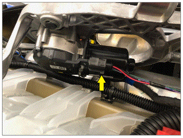
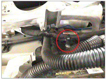
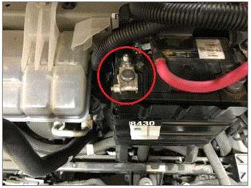
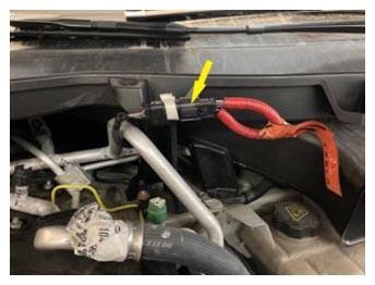
- Connect the FDU HV connector
NOTE:
1x clip, Apply slight pressure to the connector as the lever is rotated into position, Move the lever to the closed position slowly and ensure the lever teeth and manifold teeth are properly meshed, There should be a very small gap between the manifold and the connector when fully seated
 Courtesy of TESLA, INC. Courtesy of TESLA, INC.
|
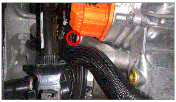
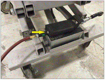
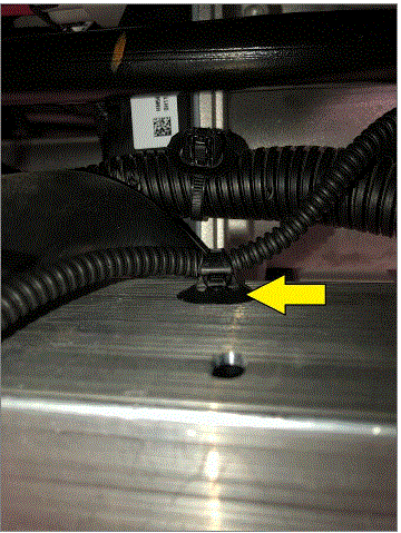
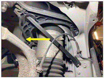
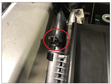
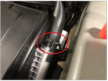
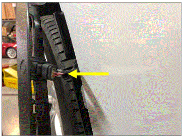
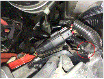
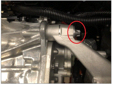
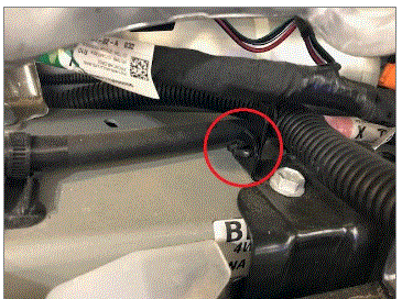
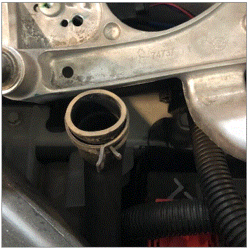
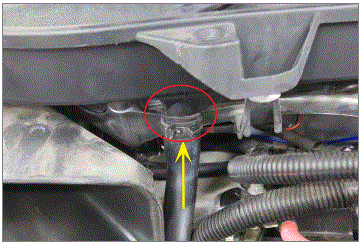
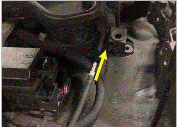
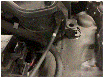
- Install the clip securing the FDU inlet hose to the FDU mount
NOTE:
1x fir tree clip
 Courtesy of TESLA, INC. Courtesy of TESLA, INC.
|
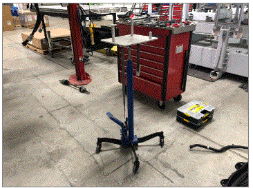
- Lower the FDU stand and underhoist stand away from the FDU
 Courtesy of TESLA, INC. Courtesy of TESLA, INC.
|
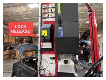
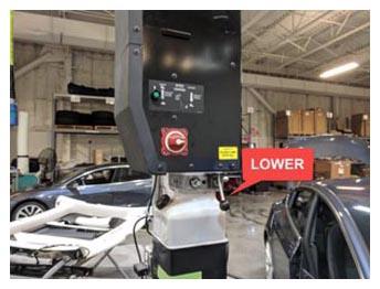
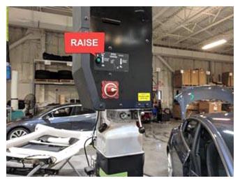
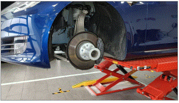
- Lower vehicle partially and set lift onto locks
NOTE:
Raise lift off locks, then hold lock release lever to keep locks free while vehicle is lowered, Set vehicle to comfortable working height
 Courtesy of TESLA, INC. Courtesy of TESLA, INC.
|
 Courtesy of TESLA, INC. Courtesy of TESLA, INC.
|
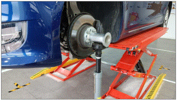
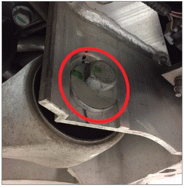
- Support the weight of the FDU
NOTE:
Ensure the FDU adapter engages the recesses in the FDU
 Courtesy of TESLA, INC. Courtesy of TESLA, INC.
|
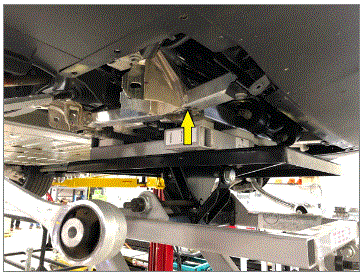
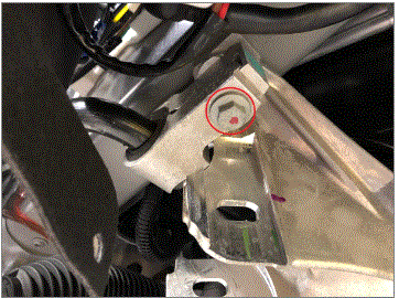
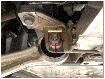
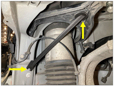
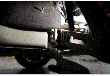
- Lift the FDU until the upper fastener securing the RH FDU mount to the body can be installed
 Courtesy of TESLA, INC. Courtesy of TESLA, INC.
|
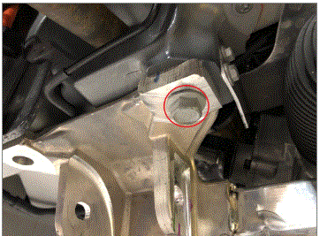
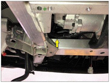
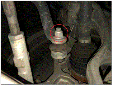
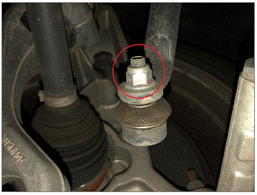
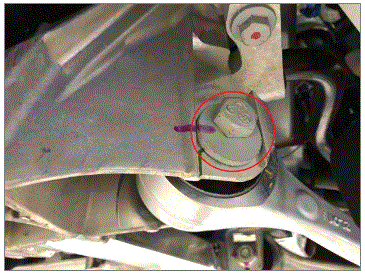
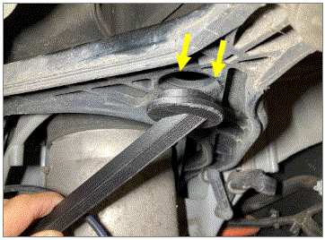
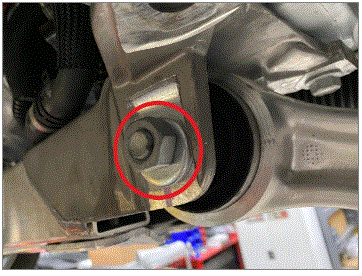
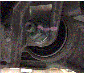
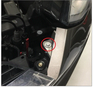
- Install the front upper fastener securing the RH FDU mount to the body
NOTE:
1x bolt, E20, 120 N.m
 Courtesy of TESLA, INC. Courtesy of TESLA, INC.
|
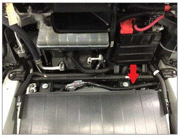
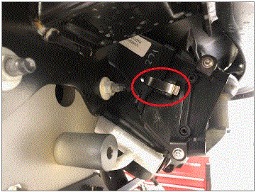
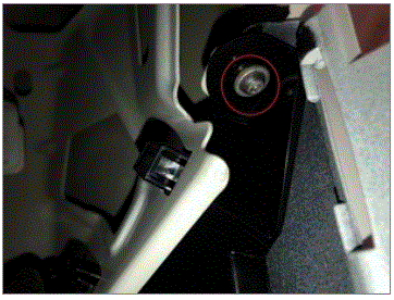
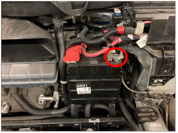
- Install the fastener securing the FDU HV harness connector to the FDU
NOTE:
1x bolt, T30, 10 N.m
 Courtesy of TESLA, INC. Courtesy of TESLA, INC.
|
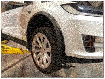
- Raise vehicle fully and lower onto locks
NOTE:
Set vehicle to comfortable working height, Make sure there's an audible click of the locks on both sides before lowering, otherwise vehicle may tilt to the side. Ensure the vehicle is stable by rocking the vehicle on the lift immediately after the tires have left the ground. Always lower the lift arms onto the locks after raising the vehicle
 Courtesy of TESLA, INC. Courtesy of TESLA, INC.
|
 Courtesy of TESLA, INC. Courtesy of TESLA, INC.
|
- Lower the FDU stand and underhoist stand away from the vehicle
Courtesy of TESLA, INC.
|
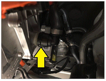
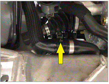
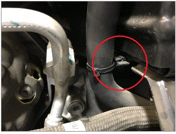
- Connect the inverter outlet coolant hose
NOTE:
1x spring clip
 Courtesy of TESLA, INC. Courtesy of TESLA, INC.
|
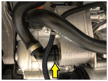
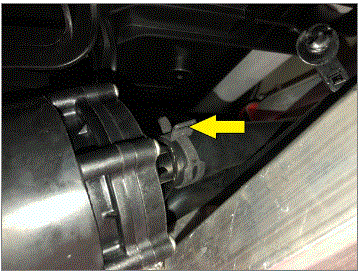
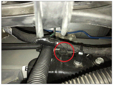
- Connect the lower coolant hose to the FDU heat exchanger
NOTE:
1x spring clip
 Courtesy of TESLA, INC. Courtesy of TESLA, INC.
|
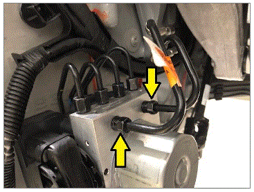
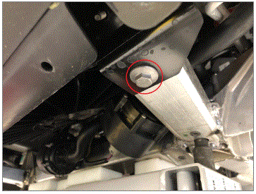
- Connect the brake lines on the ABS modulator from the master cylinder
NOTE:
2x nuts, 12 mm, 23 N.m
 Courtesy of TESLA, INC. Courtesy of TESLA, INC.
|
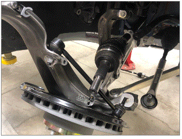
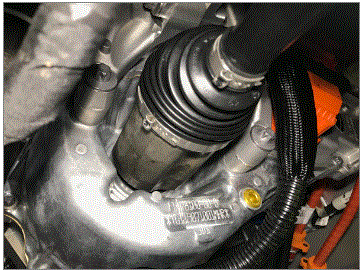
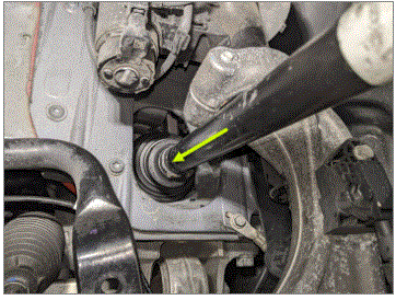
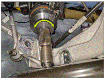
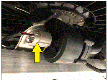
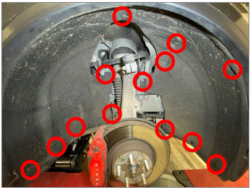
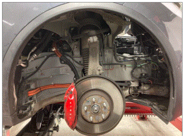
- Install the RH front axle into the front drive unit
NOTE:
Ensure the axle is fully seated into the drive unit, An audible click is heard when the C-Clip is fully engaged
 Courtesy of TESLA, INC. Courtesy of TESLA, INC.
|
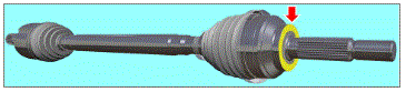
- Apply Molykote M-77 to outboard side of RH axle shaft
NOTE:
Clean if necessary, Apply no more than 1 gram to axle only
 Courtesy of TESLA, INC. Courtesy of TESLA, INC.
|
 Courtesy of TESLA, INC. Courtesy of TESLA, INC.
|
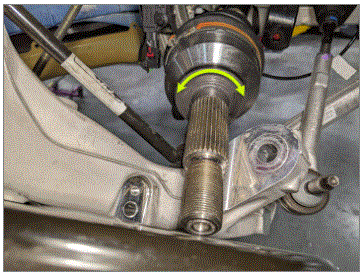
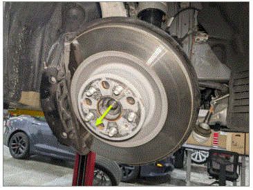
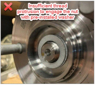
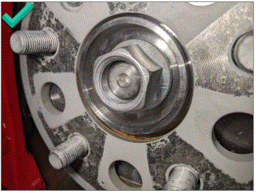
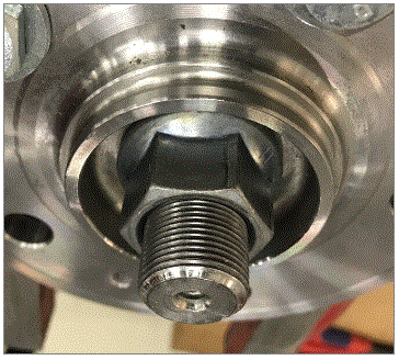
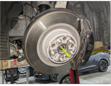
- Install RH halfshaft into hub and bearing assembly with new lock washer and nut hand tight
NOTE:
1x nut, 1x washer, 32mm, 245 Nm, Torque at later step, Use the nut without the washer to pull the shaft through hub, Then remove nut and install new washer and nut. Do not use power tools, The risk of stripping the threads is very high.
 Courtesy of TESLA, INC. Courtesy of TESLA, INC.
|
 Courtesy of TESLA, INC. Courtesy of TESLA, INC.
|
 Courtesy of TESLA, INC. Courtesy of TESLA, INC.
|
 Courtesy of TESLA, INC. Courtesy of TESLA, INC.
|
 Courtesy of TESLA, INC. Courtesy of TESLA, INC.
|
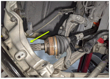
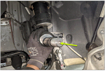
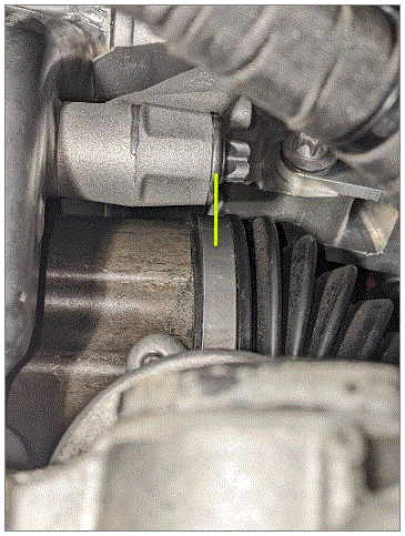
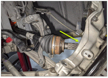
- Install the LH front axle into the front drive unit
NOTE:
Position C-clip opening at the bottom of axle to ease installation, Ensure the axle is fully seated into the drive unit, Straighten axle and apply pressure to opposite end until an audible click is heard when the C-Clip is fully engaged, If an audible click is not heard adjust shaft position and reinstall. For a visual indicator, inspect axle seal clamp is inline with base of FDU LH side mount bolt.
 Courtesy of TESLA, INC. Courtesy of TESLA, INC.
|
 Courtesy of TESLA, INC. Courtesy of TESLA, INC.
|
 Courtesy of TESLA, INC. Courtesy of TESLA, INC.
|
 Courtesy of TESLA, INC. Courtesy of TESLA, INC.
|
- Apply Molykote M-77 to outboard side of LH axle shaft
NOTE:
Clean if necessary, Apply no more than 1 gram to axle only
Courtesy of TESLA, INC.
|
 Courtesy of TESLA, INC. Courtesy of TESLA, INC.
|
- Install LH halfshaft into hub and bearing assembly with new lock washer and nut hand tight
NOTE:
1x nut, 1x washer, 32 mm, 245 N.m, Torque at later step. Use the nut without the washer to pull the shaft through hub, Then remove nut and install new washer and nut. Do not use power tools, The risk of stripping the threads is very high.
 Courtesy of TESLA, INC. Courtesy of TESLA, INC.
|
 Courtesy of TESLA, INC. Courtesy of TESLA, INC.
|
Courtesy of TESLA, INC.
|
Courtesy of TESLA, INC.
|
Courtesy of TESLA, INC.
|
- Position the subframe assembly under the vehicle for installation
 Courtesy of TESLA, INC. Courtesy of TESLA, INC.
|
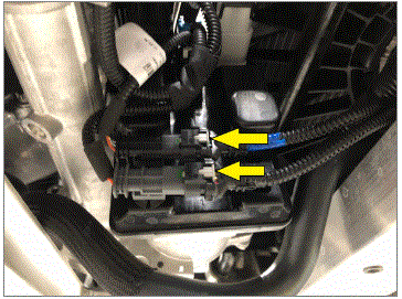
- Slowly lift the front subframe to access the power and ground connections for the steering rack and connect the electrical connections
NOTE:
2x electrical connectors, 2 stage locking connectors, Ensure the locking tab is engaged after an audible click is heard when connecting, The powertrain table may need to be adjusted as the subframe is being raised
 Courtesy of TESLA, INC. Courtesy of TESLA, INC.
|
 Courtesy of TESLA, INC. Courtesy of TESLA, INC.
|
- Raise the subframe into position to be installed
NOTE:
The powertrain table may need to be adjusted as the subframe is being raised
 Courtesy of TESLA, INC. Courtesy of TESLA, INC.
|
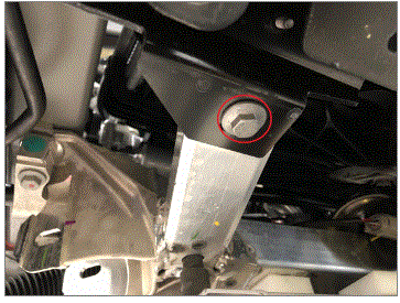
- Install the RH rear bolt securing the front subframe to the body
NOTE:
1x bolt, 18 mm, 115 N.m
 Courtesy of TESLA, INC. Courtesy of TESLA, INC.
|
- Install the LH rear bolt securing the front subframe to the body
NOTE:
1x bolt, 18 mm, 115 N.m
 Courtesy of TESLA, INC. Courtesy of TESLA, INC.
|
- Install the fastener connecting the RH stabar mount to the body through the subframe
NOTE:
1x bolt, 16 mm, 80 N.m
 Courtesy of TESLA, INC. Courtesy of TESLA, INC.
|
- Install the fastener connecting the LH stabar mount to the body through the subframe
NOTE:
1x bolt, 16 mm, 80 N.m
 Courtesy of TESLA, INC. Courtesy of TESLA, INC.
|
- Install the fastener connecting the RH side condenser bracket to the front subframe
NOTE:
1x bolt, 13 mm, 20 N.m
 Courtesy of TESLA, INC. Courtesy of TESLA, INC.
|
- Install the fastener connecting the LH side condenser bracket to the front subframe
NOTE:
1x bolt, 13 mm, 20 N.m
 Courtesy of TESLA, INC. Courtesy of TESLA, INC.
|
- Lower the powertrain table and remove it from under the vehicle
 Courtesy of TESLA, INC. Courtesy of TESLA, INC.
|
- Disconnect shop air supply from the powertrain table
 Courtesy of TESLA, INC. Courtesy of TESLA, INC.
|
- Position coolant drain container under the LH front corner of the vehicle to catch vehicle coolant
 Courtesy of TESLA, INC. Courtesy of TESLA, INC.
|
- Remove the plugs and connect the hose from the battery coolant heater to coolant pump 2 at the rear of the subframe
NOTE:
1x hose clamp, The coolant drain container may need to be moved to properly catch the residual coolant
 Courtesy of TESLA, INC. Courtesy of TESLA, INC.
|
- Remove the plugs and connect the hose from the chiller to battery coolant pump 1
NOTE:
1x hose clamp
 Courtesy of TESLA, INC. Courtesy of TESLA, INC.
|
- Install the fir tree clip securing the battery pump 1 pigtail to the subframe
NOTE:
1x fir tree clip
 Courtesy of TESLA, INC. Courtesy of TESLA, INC.
|
 Courtesy of TESLA, INC. Courtesy of TESLA, INC.
|
- Connect the chiller to battery pump 1 hose
NOTE:
1x hose clamp
 Courtesy of TESLA, INC. Courtesy of TESLA, INC.
|
- Remove coolant drain container from under the LH front of the vehicle
 Courtesy of TESLA, INC. Courtesy of TESLA, INC.
|
- Install the edge clip securing the windshield cowl drain to the subframe
NOTE:
1x edge clip
 Courtesy of TESLA, INC. Courtesy of TESLA, INC.
|
- Install the fir tree clips securing the wiring harness to the subframe
NOTE:
2x fir tree clips
 Courtesy of TESLA, INC. Courtesy of TESLA, INC.
|
 Courtesy of TESLA, INC. Courtesy of TESLA, INC.
|
- Connect battery pump 2
NOTE:
1x connector
 Courtesy of TESLA, INC. Courtesy of TESLA, INC.
|
- Connect battery pump 1
NOTE:
1x connector
 Courtesy of TESLA, INC. Courtesy of TESLA, INC.
|
- Connect the logic connectors for the steering rack
NOTE:
2x electrical connectors, 2-way connectors, Engage the grey lock after the connector is fully seated
 Courtesy of TESLA, INC. Courtesy of TESLA, INC.
|
- Install lower I-shaft onto steering gear
NOTE:
1x bolt, 13 mm, 30 N.m
 Courtesy of TESLA, INC. Courtesy of TESLA, INC.
|
 Courtesy of TESLA, INC. Courtesy of TESLA, INC.
|
- Install the RH stabar to the stabar end link
NOTE:
1x nyloc nut, 15 mm, 70 N.m, Install new nut, Counter hold stud with 5mm hex socket
 Courtesy of TESLA, INC. Courtesy of TESLA, INC.
|
- Install the LH stabar to the stabar end link
NOTE:
1x nyloc nut, 15 mm, 70 N.m, Install new nut, Counter hold stud with 5mm hex socket
 Courtesy of TESLA, INC. Courtesy of TESLA, INC.
|
- Move the RH front fore link into the subframe and install the fastener
NOTE:
1x bolt, 21 mm, 1x nut, 22 mm, 130 N.m, Leave fastener hand tight, will be torqued during alignment, Properly align the paint marks
 Courtesy of TESLA, INC. Courtesy of TESLA, INC.
|
- Move the RH front lower aft link into position and install the fastener
NOTE:
1x bolt, 21 mm, 1x nut, 22 mm, 130 N.m, Leave fastener hand tight, Will be torque during alignment, Ensure the bolt is installed with the bolt head facing the front of the vehicle
 Courtesy of TESLA, INC. Courtesy of TESLA, INC.
|
- Move the LH front fore link into the subframe and install the fastener
NOTE:
1x bolt, 21 mm, 1x nut, 22 mm, 130 N.m, Leave fastener hand tight, will be torqued during alignment, Properly align the paint marks
 Courtesy of TESLA, INC. Courtesy of TESLA, INC.
|
- Move the LH front lower aft link into position and install the fastener
NOTE:
1x bolt, 21 mm, 1x nut, 22 mm, 130 N.m, Leave fastener hand tight, Will be torque during alignment, Ensure the bolt is installed with the bolt head facing the front of the vehicle
 Courtesy of TESLA, INC. Courtesy of TESLA, INC.
|
- Install nut and bolt securing LH front air spring module to front lower aft link
NOTE:
1x bolt, 21 mm, 1x nut, 21 mm, 140 N.m, Torque at ride height on alignment rack
 Courtesy of TESLA, INC. Courtesy of TESLA, INC.
|
- Install nut and bolt securing RH front air spring module to front lower aft link
NOTE:
1x bolt, 21 mm, 1x nut, 21 mm, 140 N.m, Torque at later step
 Courtesy of TESLA, INC. Courtesy of TESLA, INC.
|
- Install skid bar to front subframe
NOTE:
4x bolts, 10 mm, 10 N.m
 Courtesy of TESLA, INC. Courtesy of TESLA, INC.
|
- Install skid plate to front subframe
NOTE:
2x bolts, 10 mm, 9 N.m
 Courtesy of TESLA, INC. Courtesy of TESLA, INC.
|
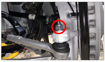
- Install nut that secures LH tie rod end to the knuckle
NOTE:
1x nyloc nut, 21 mm, 103 N.m, Install new nut
 Courtesy of TESLA, INC. Courtesy of TESLA, INC.
|
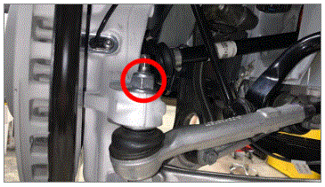
- Install the nut that secures RH tie rod end to the knuckle
NOTE:
1x nyloc nut, 21 mm, 103 N.m, Install new nut
 Courtesy of TESLA, INC. Courtesy of TESLA, INC.
|
- Lower vehicle to comfortable working height
NOTE:
Raise lift off locks, then hold lock release lever to keep locks free while vehicle is lowered
 Courtesy of TESLA, INC. Courtesy of TESLA, INC.
|
Courtesy of TESLA, INC.
|
Courtesy of TESLA, INC.
|
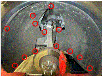
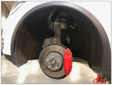
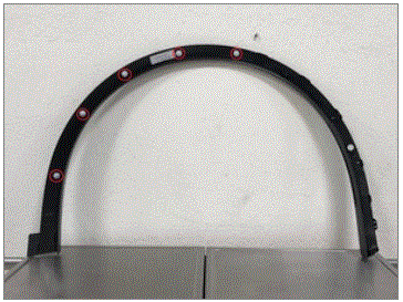
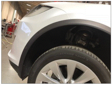
- Release LH front wheel liner from body
NOTE:
11x push clips, 2x nuts, 10 mm, 6 N.m
 Courtesy of TESLA, INC. Courtesy of TESLA, INC.
|
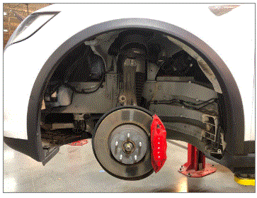
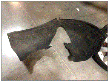
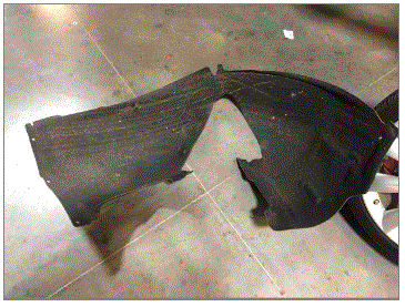
- Remove LH front wheel liner from vehicle
 Courtesy of TESLA, INC. Courtesy of TESLA, INC.
|
- Install hub jack adapter onto LH front hub
NOTE:
5x lug nuts, 21mm, Hand tight, Use modified hydraulic hub tool if correct adapter is not available
 Courtesy of TESLA, INC. Courtesy of TESLA, INC.
|
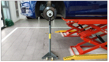
- Position and raise support stand to simulate LH front suspension at ride height
 Courtesy of TESLA, INC. Courtesy of TESLA, INC.
|
- Set ride height tool onto LH front upper control arm
 Courtesy of TESLA, INC. Courtesy of TESLA, INC.
|
 Courtesy of TESLA, INC. Courtesy of TESLA, INC.
|
- Torque LH fore link to subframe
NOTE:
1x bolt, 21 mm, 1x nut, 22 mm, 130 N.m
 Courtesy of TESLA, INC. Courtesy of TESLA, INC.
|
- Remove the existing paint mark from LH fore link
NOTE:
Clean the area thoroughly so the new marking is not confused with the previous marking
 Courtesy of TESLA, INC. Courtesy of TESLA, INC.
|
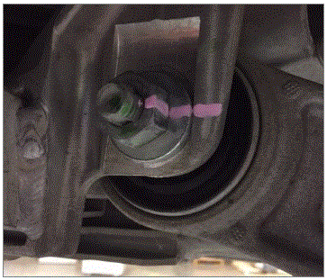
- Mark the LH fore link nut and subframe to show the component has been torqued
NOTE:
Use a high visibility paint pen when marking components
 Courtesy of TESLA, INC. Courtesy of TESLA, INC.
|
- Torque LH aft link to subframe
NOTE:
1x bolt, 21 mm, 1x nut, 22 mm, 130 N.m
 Courtesy of TESLA, INC. Courtesy of TESLA, INC.
|
- Remove the existing paint mark from LH aft link
NOTE:
Clean the area thoroughly so the new marking is not confused with the previous marking
 Courtesy of TESLA, INC. Courtesy of TESLA, INC.
|
- Mark LH front aft link bolt and subframe to show the component has been torqued
NOTE:
Use a high visibility paint pen when marking components
 Courtesy of TESLA, INC. Courtesy of TESLA, INC.
|
- Remove existing paint mark from LH air spring module bolt
NOTE:
Clean nut and surrounding area thoroughly so the new marking is not confused with the previous marking
 Courtesy of TESLA, INC. Courtesy of TESLA, INC.
|
- Torque LH air spring module nut and bolt to LH aft link assembly
NOTE:
1x bolt, 21 mm, 1x nut, 21 mm, 140 N.m
Courtesy of TESLA, INC.
|
- Mark LH air spring module nut to show the component has been torqued
NOTE:
Use a high visibility paint pen when marking components
 Courtesy of TESLA, INC. Courtesy of TESLA, INC.
|
- Remove ride height tool from LH front upper control arm
 Courtesy of TESLA, INC. Courtesy of TESLA, INC.
|
- Remove support stand from underneath LH front suspension
NOTE:
Lower stand until suspension is unladen before removal
 Courtesy of TESLA, INC. Courtesy of TESLA, INC.
|
- Remove hub jack adapter from LH front hub
NOTE:
5x lug nuts, 21 mm, Hand tight
Courtesy of TESLA, INC.
|
- Install LH front wheel liner onto vehicle
 Courtesy of TESLA, INC. Courtesy of TESLA, INC.
|
 Courtesy of TESLA, INC. Courtesy of TESLA, INC.
|
- Secure LH front wheel liner to body
NOTE:
11x push clips, 2x nuts, 10 mm, 6 N.m
Courtesy of TESLA, INC.
|
- Release RH front wheel liner from body
NOTE:
11x push clips, 2x nuts, 10 mm, 6 N.m
 Courtesy of TESLA, INC. Courtesy of TESLA, INC.
|
- Remove RH front wheel liner from vehicle
 Courtesy of TESLA, INC. Courtesy of TESLA, INC.
|
- Install hub jack adapter onto RH front hub
NOTE:
5x lug nuts, 21mm, Hand tight, Use modified hydraulic hub tool if correct adapter is not available
 Courtesy of TESLA, INC. Courtesy of TESLA, INC.
|
- Position and raise support stand to simulate RH front suspension at ride height
 Courtesy of TESLA, INC. Courtesy of TESLA, INC.
|
- Set ride height tool onto RH front upper control arm
 Courtesy of TESLA, INC. Courtesy of TESLA, INC.
|
 Courtesy of TESLA, INC. Courtesy of TESLA, INC.
|
- Torque RH fore link to subframe
NOTE:
1x bolt, 21 mm, 1x nut, 22 mm, 130 N.m
 Courtesy of TESLA, INC. Courtesy of TESLA, INC.
|
- Remove the existing paint mark from RH fore link
NOTE:
Clean the area thoroughly so the new marking is not confused with the previous marking
 Courtesy of TESLA, INC. Courtesy of TESLA, INC.
|
- Mark the RH fore link nut and subframe to show the component has been torqued
NOTE:
Use a high visibility paint pen when marking components
 Courtesy of TESLA, INC. Courtesy of TESLA, INC.
|
- Torque RH front aft link subframe
NOTE:
1x bolt, 21 mm, 1x nut, 22 mm, 130 N.m
 Courtesy of TESLA, INC. Courtesy of TESLA, INC.
|
- Remove the existing paint mark from RH aft link
NOTE:
Clean the area thoroughly so the new marking is not confused with the previous marking
 Courtesy of TESLA, INC. Courtesy of TESLA, INC.
|
- Mark the RH front aft link bolt and subframe to show the component has been torqued
NOTE:
Use a high visibility paint pen when marking components
 Courtesy of TESLA, INC. Courtesy of TESLA, INC.
|
- Torque RH air spring module nut and bolt to RH aft link assembly
NOTE:
1x bolt, 21 mm, 1x nut, 21 mm, 140 N.m
Courtesy of TESLA, INC.
|
- Remove the existing paint mark from RH air spring module
NOTE:
Clean the area thoroughly so the new marking is not confused with the previous marking
 Courtesy of TESLA, INC. Courtesy of TESLA, INC.
|
- Mark RH air spring module nut to show the component has been torqued
NOTE:
Use a high visibility paint pen when marking components
 Courtesy of TESLA, INC. Courtesy of TESLA, INC.
|
- Remove ride height tool from RH front upper control arm
 Courtesy of TESLA, INC. Courtesy of TESLA, INC.
|
- Remove support stand from underneath RH front suspension
NOTE:
Lower stand until suspension is unladen before removal
Courtesy of TESLA, INC.
|
- Remove hub jack adapter from RH front hub
NOTE:
5x lug nuts, 21 mm, Hand tight
Courtesy of TESLA, INC.
|
- Install RH front wheel liner onto vehicle
 Courtesy of TESLA, INC. Courtesy of TESLA, INC.
|
 Courtesy of TESLA, INC. Courtesy of TESLA, INC.
|
- Secure RH front wheel liner to body
NOTE:
11x push clips, 2x nuts, 10 mm, 6 N.m
Courtesy of TESLA, INC.
|
- Lower vehicle partially and set lift onto locks
NOTE:
Raise lift off locks, then hold lock release lever to keep locks free while vehicle is lowered, Set vehicle to comfortable working height
Courtesy of TESLA, INC.
|
Courtesy of TESLA, INC.
|
Courtesy of TESLA, INC.
|
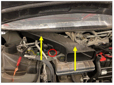
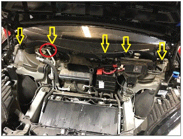
- Position the thermal beam for installation
 Courtesy of TESLA, INC. Courtesy of TESLA, INC.
|
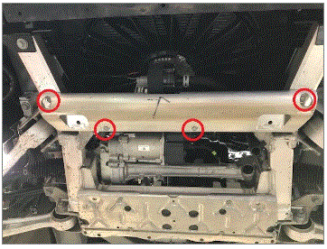
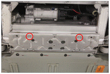
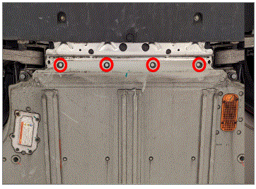
- Install bolts securing the support beam to body
NOTE:
2x bolts, 10 mm, 9 N.m
 Courtesy of TESLA, INC. Courtesy of TESLA, INC.
|
 Courtesy of TESLA, INC. Courtesy of TESLA, INC.
|
- Install the cooling fan module into the vehicle
NOTE:
Install the cooling fan module at an angle ensuring the isolators are engaged, The isolator alignment can be checked at a later step and adjusted if needed
 Courtesy of TESLA, INC. Courtesy of TESLA, INC.
|
 Courtesy of TESLA, INC. Courtesy of TESLA, INC.
|
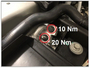
- Install the upper and lower nuts securing the high and low pressure pipes to the condenser
NOTE:
2x nuts, 13 mm, 10 N.m (upper), 20 N.m (lower), Install new O-rings
 Courtesy of TESLA, INC.
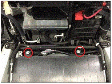
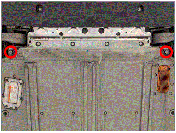
- Install bolts securing cooling fan module to support beam
NOTE:
2x bolts, 13 mm, 12 N.m
 Courtesy of TESLA, INC. Courtesy of TESLA, INC.
|
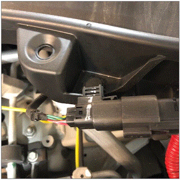
- Connect the cooling fan electrical connector
NOTE:
1x connector
 Courtesy of TESLA, INC. Courtesy of TESLA, INC.
|
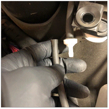
- install clip securing the cooling fan harness to cooling fan shroud
NOTE:
1x fir tree clip
 Courtesy of TESLA, INC. Courtesy of TESLA, INC.
|
- Install the coolant hose on the RH side of the radiator
NOTE:
1x hose clamp
 Courtesy of TESLA, INC. Courtesy of TESLA, INC.
|
- Remove the coolant hose clamp for the RH side radiator hose
 Courtesy of TESLA, INC. Courtesy of TESLA, INC.
|
- Install the coolant hose on the LH side of the radiator
NOTE:
1x hose clamp
 Courtesy of TESLA, INC. Courtesy of TESLA, INC.
|
- Remove the coolant hose clamp for the LH side radiator hose
 Courtesy of TESLA, INC. Courtesy of TESLA, INC.
|
- Install the active shutter assembly onto the vehicle
NOTE:
2x retaining clips
 Courtesy of TESLA, INC. Courtesy of TESLA, INC.
|
 Courtesy of TESLA, INC. Courtesy of TESLA, INC.
|
- Connect the active shutter
NOTE:
1x connector
 Courtesy of TESLA, INC. Courtesy of TESLA, INC.
|
- Install the edge clips securing the active shutter harness to the active shutter assembly
NOTE:
2x edge clips
 Courtesy of TESLA, INC. Courtesy of TESLA, INC.
|
- Install front fascia assembly to vehicle
NOTE:
1x connector, Recommend assistance
 Courtesy of TESLA, INC. Courtesy of TESLA, INC.
|
 Courtesy of TESLA, INC. Courtesy of TESLA, INC.
|
- Install bolts securing fascia to upper grill
NOTE:
2x bolts, 10 mm, 4 N.m
 Courtesy of TESLA, INC. Courtesy of TESLA, INC.
|
 Courtesy of TESLA, INC. Courtesy of TESLA, INC.
|
- Install screw securing RH fascia to fender
NOTE:
1x screw, T25, 1.5 N.m
 Courtesy of TESLA, INC. Courtesy of TESLA, INC.
|
- Install rear half of the RH front fender garnish
NOTE:
5x clips
 Courtesy of TESLA, INC. Courtesy of TESLA, INC.
|
- Connect RH front fender garnish parking sensor
NOTE:
1x connector
 Courtesy of TESLA, INC. Courtesy of TESLA, INC.
|
- Install the front half of the RH front garnish
NOTE:
8x clips, Be cautious of parking sensor, Be sure to align fender ducts
 Courtesy of TESLA, INC. Courtesy of TESLA, INC.
|
- Secure bolts for RH front wheel fairing
NOTE:
2x bolts, 10 mm, 1.5 N.m
 Courtesy of TESLA, INC. Courtesy of TESLA, INC.
|
- Secure clip for RH front wheel fairing
NOTE:
1x push clip
 Courtesy of TESLA, INC. Courtesy of TESLA, INC.
|
- Fully secure RH front wheelhouse liner to fender garnish
NOTE:
4x push clips
 Courtesy of TESLA, INC. Courtesy of TESLA, INC.
|
- Install screw securing LH fascia to fender
NOTE:
1x screw, T25, 1.5 N.m
 Courtesy of TESLA, INC. Courtesy of TESLA, INC.
|
- Install rear half of LH front fender garnish
NOTE:
5x clips
 Courtesy of TESLA, INC. Courtesy of TESLA, INC.
|
 Courtesy of TESLA, INC. Courtesy of TESLA, INC.
|
- Connect RH front fender garnish parking sensor
NOTE:
1x connector
Courtesy of TESLA, INC.
|
- Install front half of LH front garnish
NOTE:
8x clips, Be cautious of parking sensor, Be sure to align fender ducts
 Courtesy of TESLA, INC. Courtesy of TESLA, INC.
|
- Install bolts securing LH front wheel fairing to front aero shield
NOTE:
2x bolts, 10 mm, 1.5 N.m
 Courtesy of TESLA, INC. Courtesy of TESLA, INC.
|
- Install clip securing LH front wheel fairing to front aero shield
NOTE:
1x push clip
Courtesy of TESLA, INC.
|
- Fully secure LH front wheelhouse liner to fender garnish
NOTE:
4x push clips
 Courtesy of TESLA, INC. Courtesy of TESLA, INC.
|
- Lower vehicle until tires are touching ground
NOTE:
Raise lift off locks, then hold lock release lever to keep locks free while vehicle is lowered
Courtesy of TESLA, INC.
|
Courtesy of TESLA, INC.
|
Courtesy of TESLA, INC.
|
- Connect ground strap to body
NOTE:
1x nut, 13 mm, 9 N.m
 Courtesy of TESLA, INC. Courtesy of TESLA, INC.
|
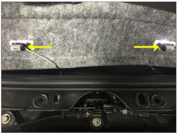
- Connect the FDU logic connector
NOTE:
1x electrical connector, engage red locking tab
 Courtesy of TESLA, INC. Courtesy of TESLA, INC.
|
 Courtesy of TESLA, INC. Courtesy of TESLA, INC.
|
 Courtesy of TESLA, INC. Courtesy of TESLA, INC.
|
- Install the edge clip securing the FDU logic harness to the connector bracket
NOTE:
1x edge clip
 Courtesy of TESLA, INC. Courtesy of TESLA, INC.
|
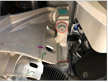
- Install the upper fastener securing the LH side isolator mount to the FDU
NOTE:
1x bolt, E14, 38 N.m
 Courtesy of TESLA, INC. Courtesy of TESLA, INC.
|
- Install A/C compressor
NOTE:
3x bolts, E10, 10 N.m
 Courtesy of TESLA, INC. Courtesy of TESLA, INC.
|
- Connect A/C compressor harness to FJB
NOTE:
1x connector
 Courtesy of TESLA, INC. Courtesy of TESLA, INC.
|
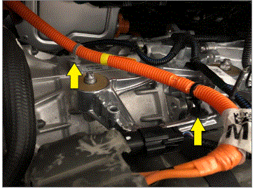
- Install the fir tree clips securing the A/C compressor HV harness to the front drive unit
NOTE:
2x fir tree clips
 Courtesy of TESLA, INC. Courtesy of TESLA, INC.
|
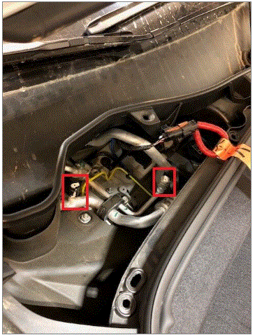
- Install both A/C lines to compressor
NOTE:
2x nuts, 10 mm, 10 N.m, Replace the O-rings
 Courtesy of TESLA, INC. Courtesy of TESLA, INC.
|
- Secure the ground connection at the A/C compressor mount bracket
NOTE:
1x bolt, T25, 7 N.m
 Courtesy of TESLA, INC. Courtesy of TESLA, INC.
|
- Connect the A/C compressor logic connector
NOTE:
1x connector
 Courtesy of TESLA, INC. Courtesy of TESLA, INC.
|
- Secure edge clip for the A/C compressor logic connector
NOTE:
1x edge clip
 Courtesy of TESLA, INC. Courtesy of TESLA, INC.
|
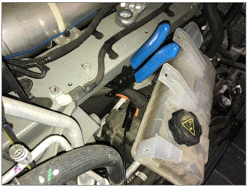
- Install air suspension reservoir to body
 Courtesy of TESLA, INC. Courtesy of TESLA, INC.
|
- Install bolts securing air suspension reservoir to body
NOTE:
4x bolts, 10 mm, 6 N.m
 Courtesy of TESLA, INC. Courtesy of TESLA, INC.
|
- Install LH front air suspension line to air suspension reservoir
NOTE:
2x clips
 Courtesy of TESLA, INC. Courtesy of TESLA, INC.
|
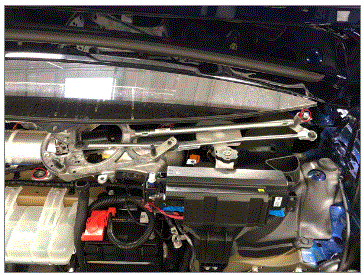
- Install wiper bracket
NOTE:
2x nuts, 13 mm, 20 N.m, 2x bolts, 13 mm, 20 N.m
 Courtesy of TESLA, INC. Courtesy of TESLA, INC.
|
- Install 12V harness onto wiper bracket
NOTE:
1x clip
 Courtesy of TESLA, INC. Courtesy of TESLA, INC.
|
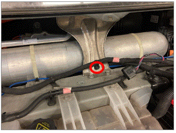
- Connect coolant hose to reservoir and remove hose clamp
NOTE:
1x coolant hose
 Courtesy of TESLA, INC. Courtesy of TESLA, INC.
|
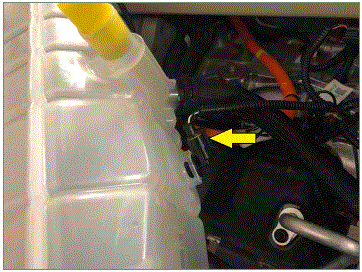
- Connect coolant reservoir level sensor
NOTE:
1x connector
 Courtesy of TESLA, INC. Courtesy of TESLA, INC.
|
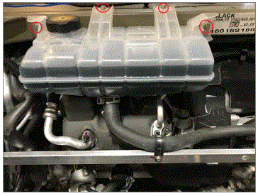
- Install fasteners securing coolant reservoir to shock tower cross member
NOTE:
4x bolts, 10 mm, 6 N.m
 Courtesy of TESLA, INC. Courtesy of TESLA, INC.
|
- Connect the wiper motor assembly electrical connector
NOTE:
1x connector
 Courtesy of TESLA, INC. Courtesy of TESLA, INC.
|
- Install wiper motor assembly
 Courtesy of TESLA, INC. Courtesy of TESLA, INC.
|
 Courtesy of TESLA, INC. Courtesy of TESLA, INC.
|
- Install cowl screen support bracket
NOTE:
3x push clips
 Courtesy of TESLA, INC. Courtesy of TESLA, INC.
|
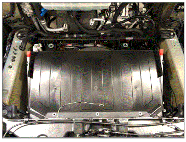
- Install battery cage assembly into vehicle
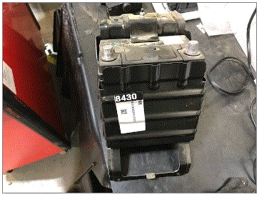 Courtesy of TESLA, INC. Courtesy of TESLA, INC.
|
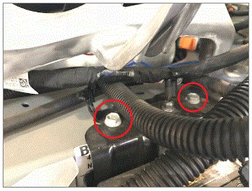
- Install bolts into top of battery cage assembly
NOTE:
2x bolts, 13 mm, 15 N.m
 Courtesy of TESLA, INC. Courtesy of TESLA, INC.
|
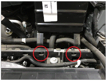
- Install bolts in bottom of battery cage assembly
NOTE:
2x bolts, 10 mm, 6 N.m
 Courtesy of TESLA, INC. Courtesy of TESLA, INC.
|
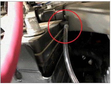
- Install battery vent tube back into battery
NOTE:
1x vent tube
 Courtesy of TESLA, INC. Courtesy of TESLA, INC.
|
- Install plastic harness clip
NOTE:
1x clip
 Courtesy of TESLA, INC. Courtesy of TESLA, INC.
|
- Install clip onto battery cage
NOTE:
1x barrel clip
 Courtesy of TESLA, INC. Courtesy of TESLA, INC.
|
- Install edge clips onto battery cage
NOTE:
2x edge clips
 Courtesy of TESLA, INC. Courtesy of TESLA, INC.
|
 Courtesy of TESLA, INC. Courtesy of TESLA, INC.
|
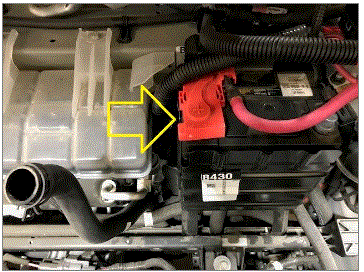
- Connect 12V positive terminal
NOTE:
1x nut, 10 mm, 5 N.m
 Courtesy of TESLA, INC. Courtesy of TESLA, INC.
|
- Install positive 12V terminal cover
 Courtesy of TESLA, INC. Courtesy of TESLA, INC.
|
- Raise vehicle fully and lower onto locks
NOTE:
Set vehicle to comfortable working height, Make sure there's an audible click of the locks on both sides before lowering, otherwise vehicle may tilt to the side, Ensure the vehicle is stable by rocking the vehicle on the lift immediately after the tires have left the ground, Always lower the lift arms onto the locks after raising the vehicle
Courtesy of TESLA, INC.
|
Courtesy of TESLA, INC.
|
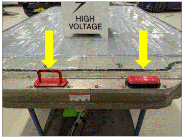
- Remove HV and LV Rapid Mate covers
NOTE:
2x covers
 Courtesy of TESLA, INC. Courtesy of TESLA, INC.
|
- Position HV battery underneath vehicle
 Courtesy of TESLA, INC. Courtesy of TESLA, INC.
|
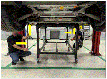
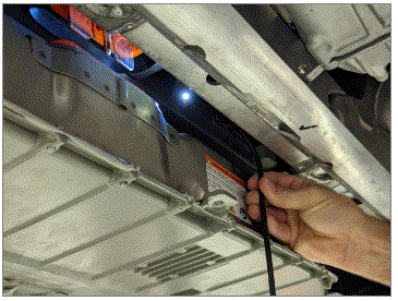
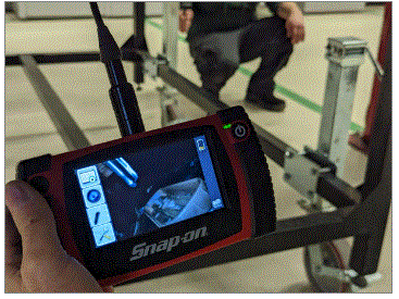
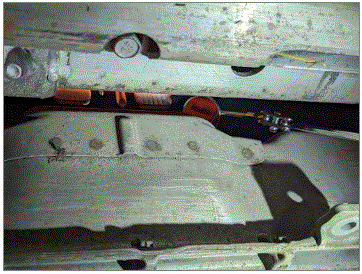
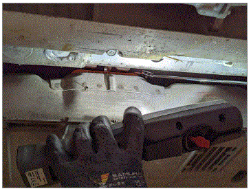
- Lower vehicle onto HV battery pack
NOTE:
Before lowering fully use assistance to align the pack using the alignment rods and guide via the borescope camera or a flexible inspection mirror checking HV and LV rapid mates
Courtesy of TESLA, INC.
|
 Courtesy of TESLA, INC. Courtesy of TESLA, INC.
|
 Courtesy of TESLA, INC. Courtesy of TESLA, INC.
|
 Courtesy of TESLA, INC. Courtesy of TESLA, INC.
|
 Courtesy of TESLA, INC. Courtesy of TESLA, INC.
|
 Courtesy of TESLA, INC. Courtesy of TESLA, INC.
|
- Install front bolts for HV battery with battery powered drill
NOTE:
4x patch bolts, 13 mm, 30 N.m, Install new patch bolts, Do not over tighten bolts, Torque at later step
 Courtesy of TESLA, INC. Courtesy of TESLA, INC.
|
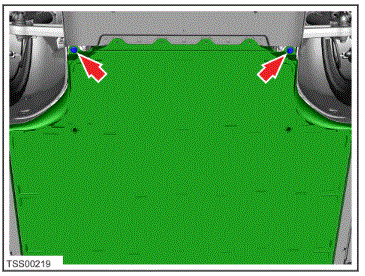
- Install 21mm bolts at front of HV battery with battery powered drill
NOTE:
2x bolts, 21 mm, 115 N.m, Install new bolts, Do not over tighten bolts, Torque at later step
 Courtesy of TESLA, INC. Courtesy of TESLA, INC.
|
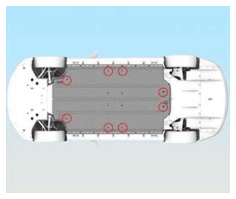
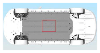
- Install eight outer center bolts with battery powered drill
NOTE:
8x patch bolts, E12, 38 N.m, Install new patch bolts, Do not over tighten bolts, Torque at later step
 Courtesy of TESLA, INC. Courtesy of TESLA, INC.
|
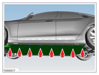
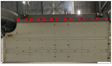
- Install LH rocker bolts with battery powered drill
NOTE:
8x patch bolts, 13 mm, 55 N.m, Install new patch bolts, Do not over tighten bolts, Torque at later step
 Courtesy of TESLA, INC. Courtesy of TESLA, INC.
|
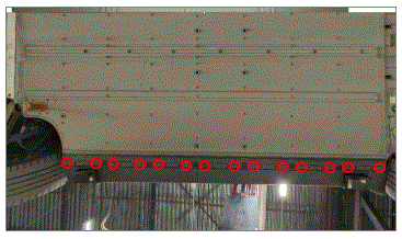
- Install RH rocker bolts with battery powered drill
NOTE:
8x patch bolts, 13 mm, 55 N.m, Install new patch bolts, Do not over tighten bolts, Torque at later step
 Courtesy of TESLA, INC. Courtesy of TESLA, INC.
|
- Torque rocker HV battery bolts on both sides
NOTE:
16x patch bolts, 13 mm, 55 N.m
Courtesy of TESLA, INC.
|
Courtesy of TESLA, INC.
|
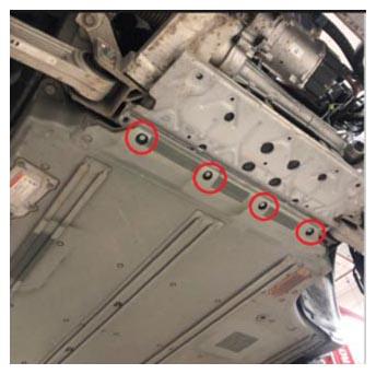
- Torque remaining HV battery bolts
NOTE:
8x bolts, E12, 38 N.m, 2x bolts, 21 mm, 115 N.m, 4x bolts, 13 mm, 30 N.m
 Courtesy of TESLA, INC. Courtesy of TESLA, INC.
|
 Courtesy of TESLA, INC. Courtesy of TESLA, INC.
|
 Courtesy of TESLA, INC. Courtesy of TESLA, INC.
|
- Raise vehicle off of HV battery
 Courtesy of TESLA, INC. Courtesy of TESLA, INC.
|
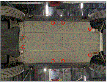
- Install inner center HV battery bolts with battery powered drill
NOTE:
4x patch bolts, E12, 38 N.m, Install new patch bolts, Do not over tighten bolts
 Courtesy of TESLA, INC. Courtesy of TESLA, INC.
|
- Torque the inner center HV battery bolts
NOTE:
4x patch bolts, E12, 38 N.m
Courtesy of TESLA, INC.
|
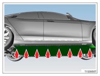
- Install LH ski side covers
NOTE:
14x clips, 3x covers
 Courtesy of TESLA, INC. Courtesy of TESLA, INC.
|
- Install RH ski side covers
NOTE:
14x clips, 3x covers
 Courtesy of TESLA, INC. Courtesy of TESLA, INC.
|
- Install front bash plate extrusion
NOTE:
2x bolts, T30, 16 Nm
 Courtesy of TESLA, INC. Courtesy of TESLA, INC.
|
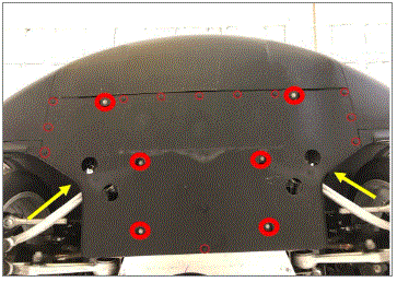
- Install front aero shield
NOTE:
6x bolts, 10 mm, 3 N.m, 14x clips
 Courtesy of TESLA, INC. Courtesy of TESLA, INC.
|
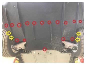
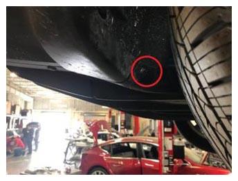
- Install mid aero shield
NOTE:
20x bolts, 10 mm, 4 N.m, 2x push clips
 Courtesy of TESLA, INC. Courtesy of TESLA, INC.
|
 Courtesy of TESLA, INC. Courtesy of TESLA, INC.
|
- Install LH shear plate
NOTE:
3x screws, T25, 6 N.m, 1x bolt, 10 mm, 4 N.m, 2x push clips, Install new nyloc nut, 15 mm, 35 N.m
 Courtesy of TESLA, INC. Courtesy of TESLA, INC.
|
- Install RH shear plate
NOTE:
3x screws, T25, 6 N.m, 1x bolt, 10 mm, 4 N.m, 2x push clips, Install new nyloc nut, 15 mm, 35 N.m
 Courtesy of TESLA, INC. Courtesy of TESLA, INC.
|
- Lower vehicle fully
Courtesy of TESLA, INC.
|
Courtesy of TESLA, INC.
|
- Connect first responder loop and then 12V negative terminal
NOTE:
1x connector, 1x nut, 10 mm, 5 N.m
 Courtesy of TESLA, INC. Courtesy of TESLA, INC.
|
 Courtesy of TESLA, INC. Courtesy of TESLA, INC.
|
- Install HEPA filter duct
NOTE:
1x clip
 Courtesy of TESLA, INC. Courtesy of TESLA, INC.
|
- Remove wiper cowl screen panel
NOTE:
5x push clips, 1x windshield washer hose, 1x drain hose clamp
 Courtesy of TESLA, INC. Courtesy of TESLA, INC.
|
 Courtesy of TESLA, INC. Courtesy of TESLA, INC.
|
 Courtesy of TESLA, INC. Courtesy of TESLA, INC.
|
 Courtesy of TESLA, INC. Courtesy of TESLA, INC.
|
- Connect cowl drain hose onto cowl trim
NOTE:
1x clamp
 Courtesy of TESLA, INC. Courtesy of TESLA, INC.
|
- Connect cowl screen washer supply hose
NOTE:
1x one way valve
 Courtesy of TESLA, INC. Courtesy of TESLA, INC.
|
 Courtesy of TESLA, INC. Courtesy of TESLA, INC.
|
- Install RH wiper arm
NOTE:
2x nuts, 17 mm, 35 N.m, Align tip of wiper blade to mark on windshield, connect washer hose at cowl
 Courtesy of TESLA, INC. Courtesy of TESLA, INC.
|
- Install LH wiper arm
NOTE:
1x nut, 17 mm, 35 N.m, Align tip of wiper blade to mark on windshield, connect washer hose at cowl
 Courtesy of TESLA, INC. Courtesy of TESLA, INC.
|
- Install LH outer hood hinge cover
NOTE:
2x clips
 Courtesy of TESLA, INC. Courtesy of TESLA, INC.
|
- Install RH outer hood hinge cover
NOTE:
2x clips
 Courtesy of TESLA, INC. Courtesy of TESLA, INC.
|
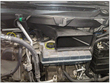
- Remove coolant reservoir cap
NOTE:
1x cap
 Courtesy of TESLA, INC. Courtesy of TESLA, INC.
|
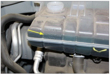
- Fill reservoir to "NOM" line
NOTE:
Monitor the coolant level once the purge routine is running, adding coolant as required using G-48 coolant
 Courtesy of TESLA, INC. Courtesy of TESLA, INC.
|
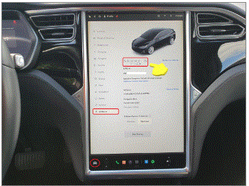
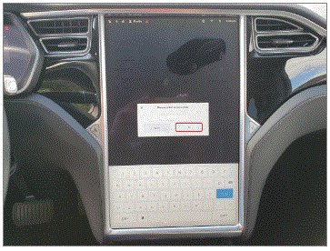
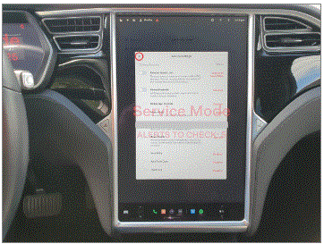
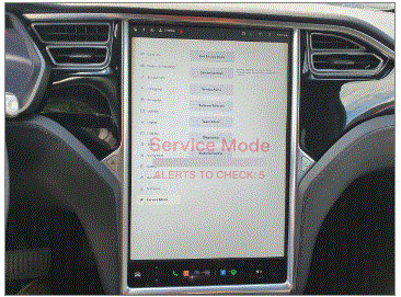
- Place vehicle in service mode with touchscreen
NOTE:
Select Controls > Software, Touch and hold "Model" for 2 seconds then release, Use the screen keyboard to type "service" into dialog box and select "OK" button, Select "X" at upper left corner to exit "Service Settings" dialogue box
 Courtesy of TESLA, INC. Courtesy of TESLA, INC.
|
 Courtesy of TESLA, INC. Courtesy of TESLA, INC.
|
 Courtesy of TESLA, INC. Courtesy of TESLA, INC.
|
 Courtesy of TESLA, INC. Courtesy of TESLA, INC.
|
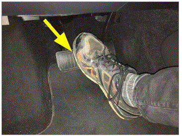
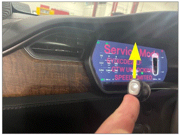
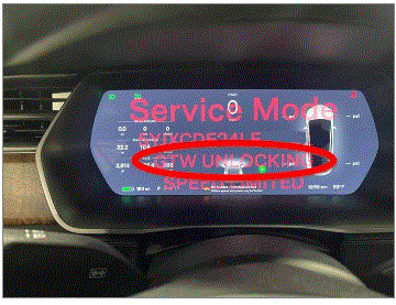
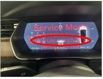
- Unlock vehicle Gateway
NOTE:
After vehicle has been put into "Service Mode", hold down the brake pedal, while holding down break pedal simultaneously hold the turn signal stalk fully up for at least 10 seconds, "GTW UNLOCKING" should pop up on the instrument cluster right below the VIN during these 10 seconds, once gateway is unlocked "GTW UNLOCKED 899" will be displayed on the instrument cluster underneath the VIN, the gateway will remain unlocked for 15 minutes, follow steps on Toolbox article https://toolbox.teslamotors.com/articles/5582900 for any additional information
 Courtesy of TESLA, INC. Courtesy of TESLA, INC.
|
 Courtesy of TESLA, INC. Courtesy of TESLA, INC.
|
 Courtesy of TESLA, INC. Courtesy of TESLA, INC.
|
 Courtesy of TESLA, INC. Courtesy of TESLA, INC.
|
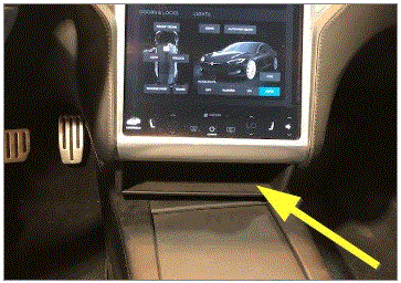
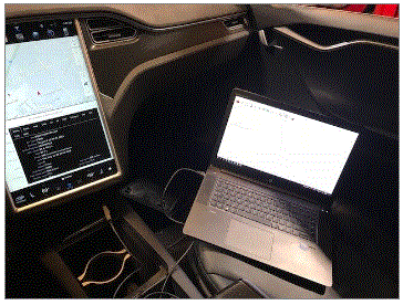
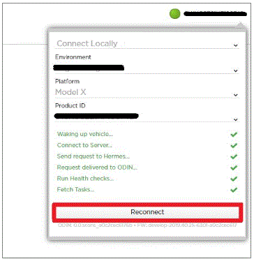
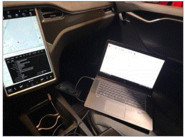
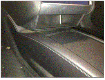
- Remove cubby under MCU and connect laptop to vehicle with a tethered Ethernet connection via Toolbox 3
NOTE:
1x connector, 2x clips, Remove cubby under MCU and connect laptop to vehicle, Open Toolbox 3 website and establish connection to vehicle: https://toolbox.teslamotors.com, Select connection status icon at top right corner, and select Connect Locally (icon will turn green when vehicle is connected)
 Courtesy of TESLA, INC. Courtesy of TESLA, INC.
|
 Courtesy of TESLA, INC. Courtesy of TESLA, INC.
|
 Courtesy of TESLA, INC. Courtesy of TESLA, INC.
|
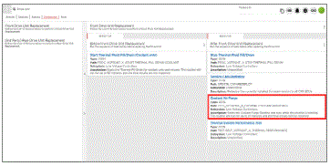
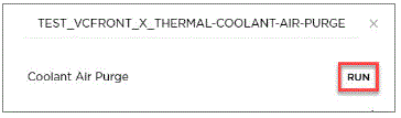
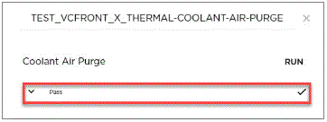
- Select TEST_VCFRONT_X_THERMAL-COOLANT-AIR-PURGE, click "Run", and allow routine to complete
NOTE:
Make sure vehicle is not in drive state, Routine is still running despite the stop message, Coolant pumps will be audible, Test lasts approximately 10 mins, Putting vehicle into drive state will stop this routine, Monitor levels as required
 Courtesy of TESLA, INC. Courtesy of TESLA, INC.
|
 Courtesy of TESLA, INC. Courtesy of TESLA, INC.
|
 Courtesy of TESLA, INC. Courtesy of TESLA, INC.
|
- Top off the reservoir to the "NOM" line with G-48 coolant
NOTE:
Ensure coolant is filled to nominal level
Courtesy of TESLA, INC.
|
- Install coolant reservoir cap
NOTE:
1x cap
 Courtesy of TESLA, INC. Courtesy of TESLA, INC.
|
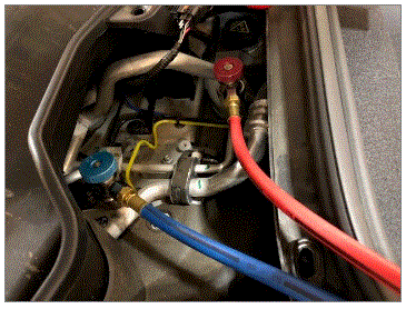
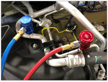
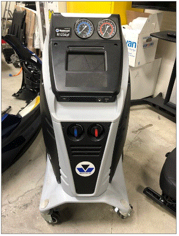
- Connect hoses to vehicle and perform A/C vacuum and leak test
NOTE:
(Touch time only) 30 minute vacuum, 10 minute leak test. Ensure quick connects are fully engaged, turn the connector dials clockwise to fully connect to A/C service ports
 Courtesy of TESLA, INC. Courtesy of TESLA, INC.
|
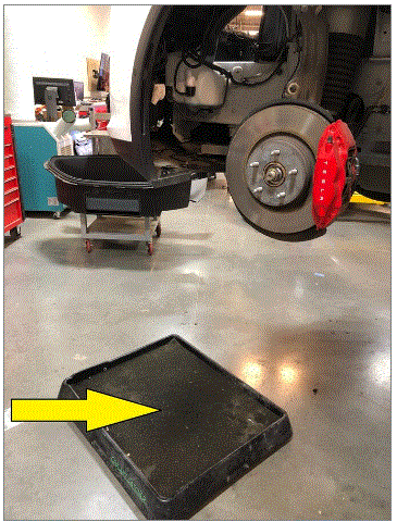
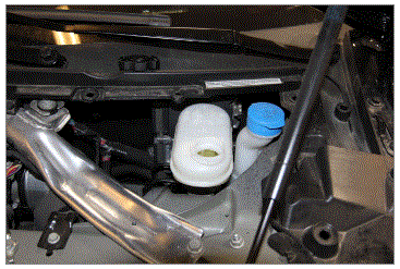
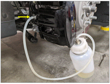
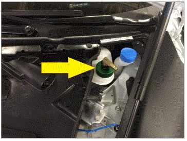
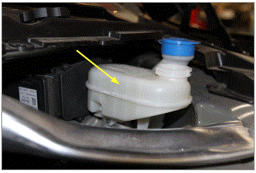
- Fill brake bleeder reservoir
 Courtesy of TESLA, INC. Courtesy of TESLA, INC.
|
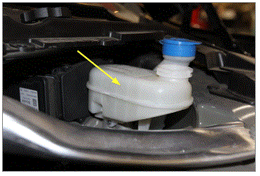
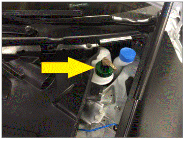
- Clean area around brake fluid reservoir and remove cap
 Courtesy of TESLA, INC. Courtesy of TESLA, INC.
|
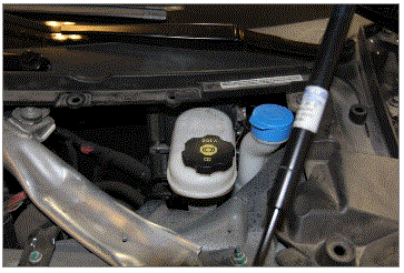
- Top off reservoir
NOTE:
If necessary
 Courtesy of TESLA, INC. Courtesy of TESLA, INC.
|
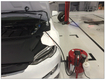
- Install pressure bleeder on reservoir
 Courtesy of TESLA, INC. Courtesy of TESLA, INC.
|
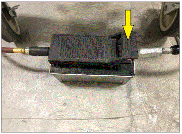
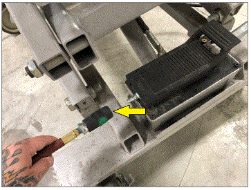
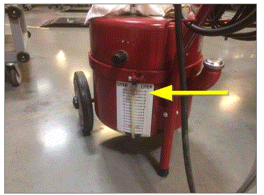
- Connect bleeder to adapter and set pressure to 30psi
 Courtesy of TESLA, INC. Courtesy of TESLA, INC.
|
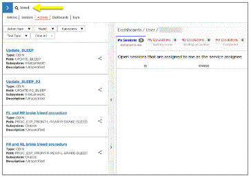
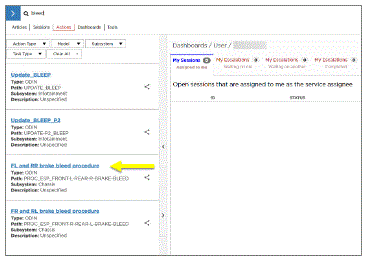
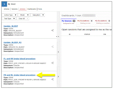
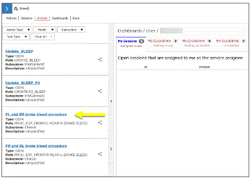
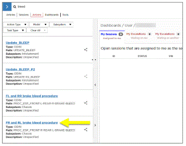
- Select "Actions" tab and search for '"bleed"
 Courtesy of TESLA, INC. Courtesy of TESLA, INC.
|
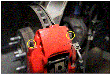
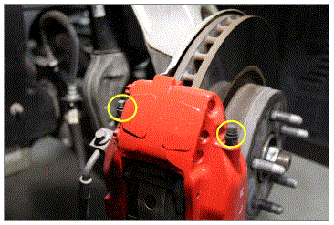
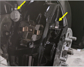
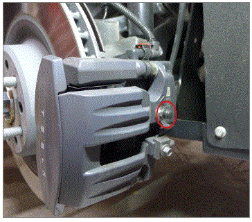
- Remove the bleeder covers from LH front caliper
NOTE:
2x covers
 Courtesy of TESLA, INC. Courtesy of TESLA, INC.
|
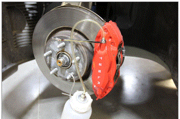
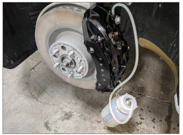
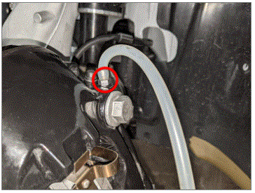
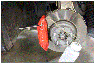
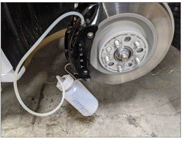
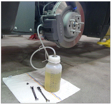
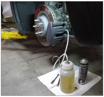
- Install the fluid catching bottle to LH front caliper outer bleeder valve and loosen the valve
NOTE:
Let the brake fluid drain for about 10 seconds or so before starting Toolbox bleeding routine
 Courtesy of TESLA, INC. Courtesy of TESLA, INC.
|
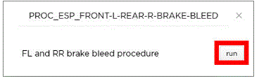
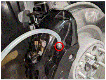
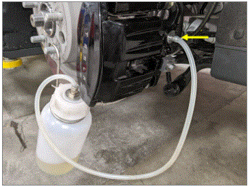
- Open the LH front outer brake caliper bleeding valve then Click the play button next to PROC_ESP_FRONT-L-REAR-R-BRAKE-BLEED and select "Run" to start the ESP and then close the bleeding valve once the pump stops running
NOTE:
1x bleeding valve, 11 mm, 18 N.m
 Courtesy of TESLA, INC. Courtesy of TESLA, INC.
|
 Courtesy of TESLA, INC. Courtesy of TESLA, INC.
|
 Courtesy of TESLA, INC. Courtesy of TESLA, INC.
|
- Open the LH front inner brake caliper bleeding valve then Click the play button next to PROC_ESP_FRONT-L-REAR-R-BRAKE-BLEED and select "Run" to start the ESP and then close the bleeding valve once the pump stops running
NOTE:
1x bleeding valves, 11 mm, 18 N.m
 Courtesy of TESLA, INC. Courtesy of TESLA, INC.
|
 Courtesy of TESLA, INC. Courtesy of TESLA, INC.
|
 Courtesy of TESLA, INC. Courtesy of TESLA, INC.
|
 Courtesy of TESLA, INC. Courtesy of TESLA, INC.
|
- Remove the fluid catching bottle, Torque LH front brake caliper bleeding valves and install covers
NOTE:
2x bleeding valves, 11 mm, 18 N.m, 2x covers
 Courtesy of TESLA, INC. Courtesy of TESLA, INC.
|
 Courtesy of TESLA, INC. Courtesy of TESLA, INC.
|
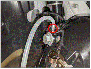
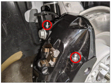
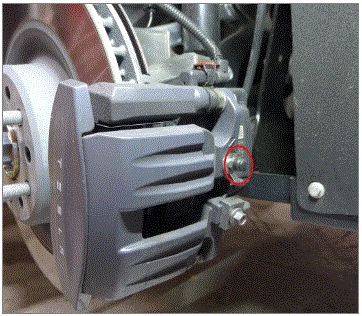
- Remove the bleeder covers from RH front caliper
NOTE:
2x covers
 Courtesy of TESLA, INC. Courtesy of TESLA, INC.
|
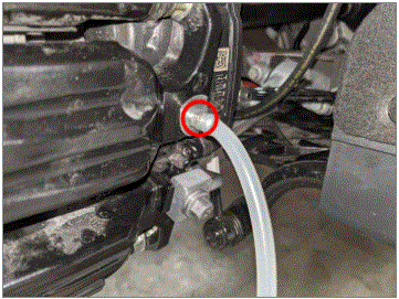
- Install the fluid catching bottle to RH front caliper outer bleeder valve and loosen the valve
NOTE:
Let the brake fluid drain for about 10 seconds or so before starting Toolbox bleeding routine
 Courtesy of TESLA, INC. Courtesy of TESLA, INC.
|
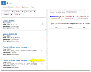
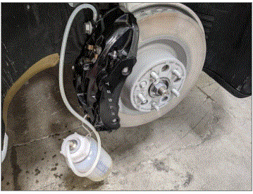
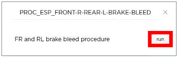
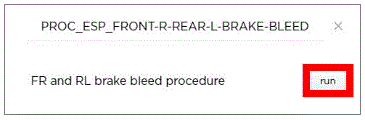
- Open the RH front outer brake caliper bleeding valve then Click the play button next to PROC_ESP_FRONT-R-REAR-L-BRAKE-BLEED and select "Run" to start the ESP and then close the bleeding valve once the pump stops running
NOTE:
Note 1x bleeding valve, 11 mm, 18 N.m
 Courtesy of TESLA, INC. Courtesy of TESLA, INC.
|
 Courtesy of TESLA, INC. Courtesy of TESLA, INC.
|
 Courtesy of TESLA, INC. Courtesy of TESLA, INC.
|
 Courtesy of TESLA, INC. Courtesy of TESLA, INC.
|
- Open the RH front inner brake caliper bleeding valve then Click the play button next to PROC_ESP_FRONT-R-REAR-L-BRAKE-BLEED and select "Run" to start the ESP and then close the bleeding valve once the pump stops running
NOTE:
1x bleeding valves, 11 mm, 18 N.m
 Courtesy of TESLA, INC. Courtesy of TESLA, INC.
|
 Courtesy of TESLA, INC. Courtesy of TESLA, INC.
|
 Courtesy of TESLA, INC. Courtesy of TESLA, INC.
|
 Courtesy of TESLA, INC. Courtesy of TESLA, INC.
|
- Remove the fluid catching bottle, Torque RH front brake caliper bleeding valves and install covers
NOTE:
2x bleeding valves, 11 mm, 18 N.m, 2x covers
 Courtesy of TESLA, INC. Courtesy of TESLA, INC.
|
 Courtesy of TESLA, INC. Courtesy of TESLA, INC.
|
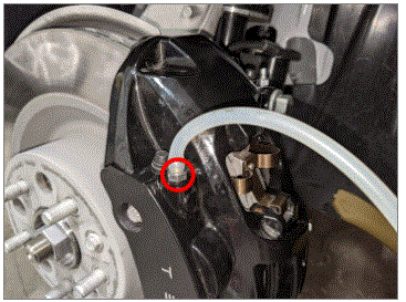
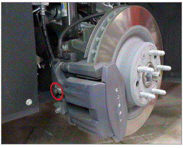
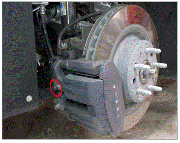
- Remove the bleeder cover from RH rear caliper
NOTE:
1x cover
 Courtesy of TESLA, INC. Courtesy of TESLA, INC.
|
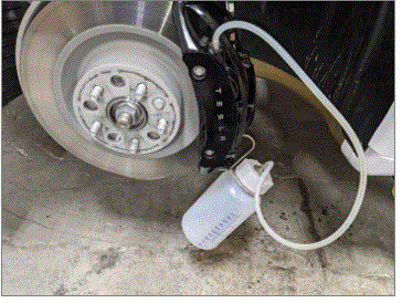
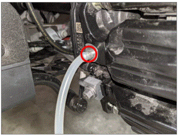
- Install the fluid catching bottle to RH rear caliper bleeder valve and loosen the valve
NOTE:
Let the brake fluid drain for about 10 seconds or so before starting Toolbox bleeding routine
 Courtesy of TESLA, INC. Courtesy of TESLA, INC.
|
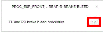
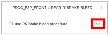
- Open the RH rear brake caliper bleeding valve then Click the play button next to PROC_ESP_FRONT-L-REAR-R-BRAKE-BLEED and select "Run" to start the ESP and then close the bleeding valve once the pump stops running
NOTE:
1x bleeding valve, 10 mm, 18 N.m
 Courtesy of TESLA, INC. Courtesy of TESLA, INC.
|
 Courtesy of TESLA, INC. Courtesy of TESLA, INC.
|
 Courtesy of TESLA, INC. Courtesy of TESLA, INC.
|
 Courtesy of TESLA, INC. Courtesy of TESLA, INC.
|
- Remove the fluid catching bottle, Torque RH rear brake caliper bleeding valve and install cover
NOTE:
1x bleeding valve, 10 mm, 18 N.m, 1x cover
 Courtesy of TESLA, INC. Courtesy of TESLA, INC.
|
- Remove the bleeder cover from LH rear caliper
NOTE:
1x cover
 Courtesy of TESLA, INC. Courtesy of TESLA, INC.
|
- Install the fluid catching bottle to LH rear caliper bleeder valve and loosen the valve
NOTE:
Let the brake fluid drain for about 10 seconds or so before starting Toolbox bleeding routine
 Courtesy of TESLA, INC. Courtesy of TESLA, INC.
|
- Open the LH rear brake caliper bleeding valve then Click the play button next to PROC_ESP_FRONT-R-REAR-L-BRAKE-BLEED and select "Run" to start the ESP and then close the bleeding valve once the pump stops running
NOTE:
1x bleeding valve, 10 mm, 18 N.m
 Courtesy of TESLA, INC. Courtesy of TESLA, INC.
|
 Courtesy of TESLA, INC. Courtesy of TESLA, INC.
|
 Courtesy of TESLA, INC. Courtesy of TESLA, INC.
|
 Courtesy of TESLA, INC. Courtesy of TESLA, INC.
|
- Remove the fluid catching bottle, Torque LH rear brake caliper bleeding valve and install cover
NOTE:
1x bleeding valve, 10 mm, 18 N.m, 1x cover
 Courtesy of TESLA, INC. Courtesy of TESLA, INC.
|
- Release pressure and remove brake pressure bleed adapter from vehicle
 Courtesy of TESLA, INC. Courtesy of TESLA, INC.
|
- Check fluid level
NOTE:
Top off if needed
 Courtesy of TESLA, INC. Courtesy of TESLA, INC.
|
- Install brake reservoir cap
NOTE:
1x cap
 Courtesy of TESLA, INC. Courtesy of TESLA, INC.
|
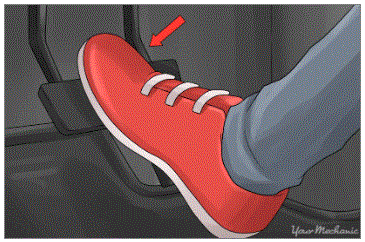
- Pump the brake pedal few times to ensure the pedal feels normal
 Courtesy of TESLA, INC. Courtesy of TESLA, INC.
|
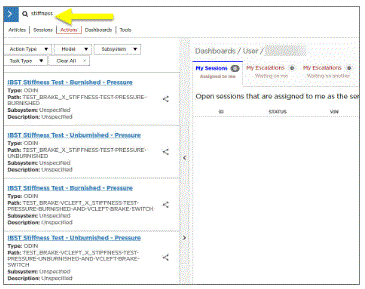
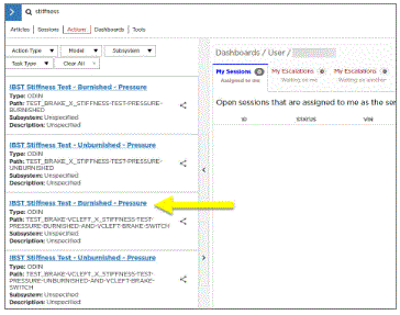
- Select "Actions" tab and search for '"Stiffness"
 Courtesy of TESLA, INC. Courtesy of TESLA, INC.
|
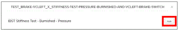
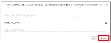
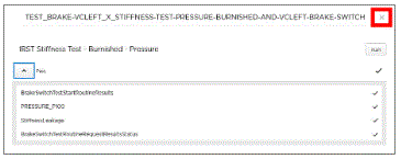
- Select TEST_BRAKE-VCLEFT_X_STIFFNESS-TEST-PRESSURE-BURNISHED-AND-VCLEFT-BRAKE-SWITCH, click "Run", and allow routine to complete
NOTE:
Select "Submit" without additional input when prompted, Select "X" at top right of window to close once complete
 Courtesy of TESLA, INC. Courtesy of TESLA, INC.
|
 Courtesy of TESLA, INC. Courtesy of TESLA, INC.
|
 Courtesy of TESLA, INC. Courtesy of TESLA, INC.
|
 Courtesy of TESLA, INC. Courtesy of TESLA, INC.
|
- Disconnect Toolbox from vehicle and install cubby under the MCU
NOTE:
1x connector, 2x clips
 Courtesy of TESLA, INC. Courtesy of TESLA, INC.
|
 Courtesy of TESLA, INC. Courtesy of TESLA, INC.
|
- Raise vehicle partially and lower onto locks
NOTE:
Set vehicle to comfortable working height, Make sure there's an audible click of the locks on both sides before lowering, otherwise vehicle may tilt to the side
Courtesy of TESLA, INC.
|
Courtesy of TESLA, INC.
|
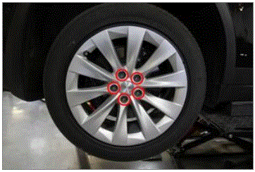
- Install LH front wheel
NOTE:
5x nuts, 21 mm, 175 N.m, Start lug nuts by hand before using power tool
 Courtesy of TESLA, INC. Courtesy of TESLA, INC.
|
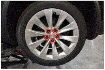
- Install RH front wheel
NOTE:
5x nuts, 21 mm, 175 N.m, Thread nuts on by hand
 Courtesy of TESLA, INC. Courtesy of TESLA, INC.
|
- Install RH rear wheel
NOTE:
5x nuts, 21 mm, 175 N.m
Courtesy of TESLA, INC.
|
 Courtesy of TESLA, INC. Courtesy of TESLA, INC.
|
- Install LH rear wheel
NOTE:
5x nuts, 21 mm, 175 N.m
Courtesy of TESLA, INC.
|
 Courtesy of TESLA, INC. Courtesy of TESLA, INC.
|
- Lower vehicle until tires are touching ground
NOTE:
Raise lift off locks, then hold lock release lever to keep locks free while vehicle is lowered
Courtesy of TESLA, INC.
|
Courtesy of TESLA, INC.
|
Courtesy of TESLA, INC.
|
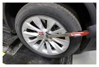
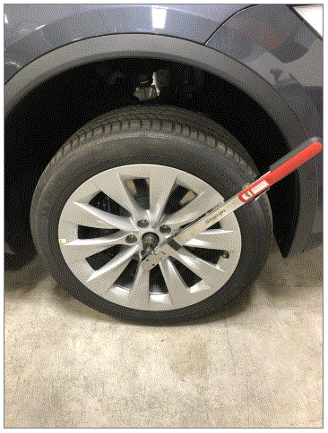
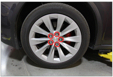
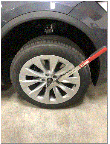
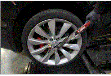
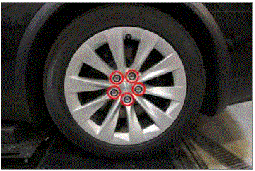
- Torque RH front wheel
NOTE:
5x nuts, 21 mm, 175 N.m
 Courtesy of TESLA, INC. Courtesy of TESLA, INC.
|
- Install RH front lug nut covers
NOTE:
5x covers
 Courtesy of TESLA, INC. Courtesy of TESLA, INC.
|
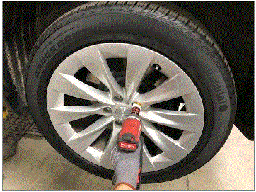
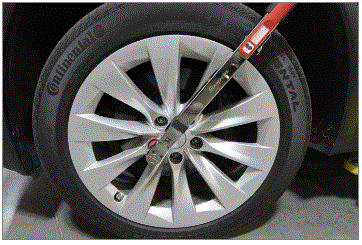
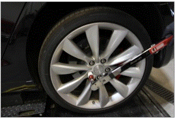
- Torque RH front axle nut
NOTE:
1x nut, 32 mm, 245 N.m
 Courtesy of TESLA, INC. Courtesy of TESLA, INC.
|
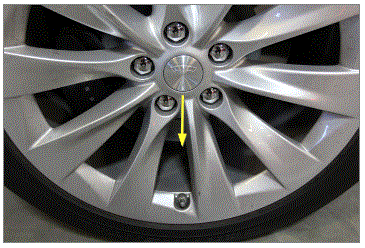
- Install RH front wheel center cap
NOTE:
1x cap, Verify emblem is aligned with valve stem
 Courtesy of TESLA, INC. Courtesy of TESLA, INC.
|
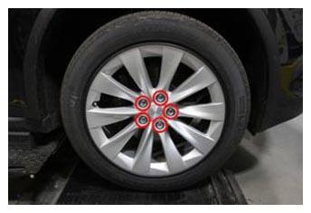
- Torque LH front wheel
NOTE:
5x nuts, 21 mm, 175 N.m
 Courtesy of TESLA, INC. Courtesy of TESLA, INC.
|
- Install LH front lug nut covers
NOTE:
5x covers
 Courtesy of TESLA, INC. Courtesy of TESLA, INC.
|
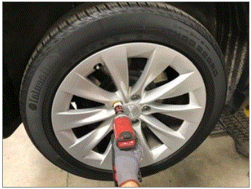
- Torque LH front axle nut
NOTE:
1x nut, 32 mm, 245 N.m
 Courtesy of TESLA, INC. Courtesy of TESLA, INC.
|
- Install LH front wheel center cap
NOTE:
1x cap, Verify emblem is aligned with valve stem
Courtesy of TESLA, INC.
|
- Torque RH rear wheel
NOTE:
5x nuts, 21 mm, 175 N.m
 Courtesy of TESLA, INC. Courtesy of TESLA, INC.
|
- Install RH rear lug nut covers
NOTE:
5x covers
Courtesy of TESLA, INC.
|
- Torque LH rear wheel
NOTE:
5x nuts, 21 mm, 175 N.m
 Courtesy of TESLA, INC. Courtesy of TESLA, INC.
|
- Install LH rear lug nut covers
NOTE:
5x covers
 Courtesy of TESLA, INC. Courtesy of TESLA, INC.
|
- Install HEPA filter housing
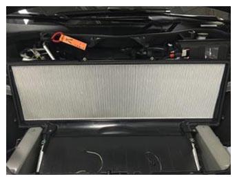 Courtesy of TESLA, INC. Courtesy of TESLA, INC.
|
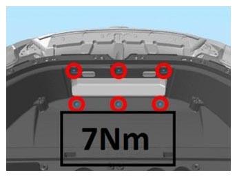
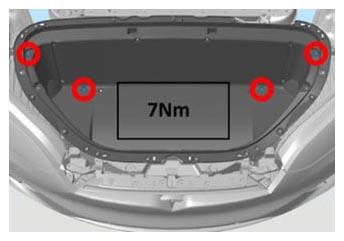
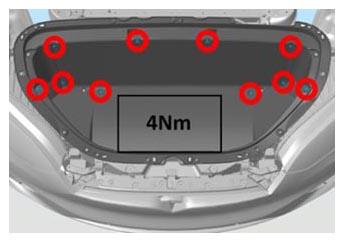
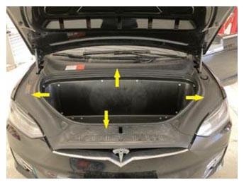
- Install underhood storage unit
NOTE:
10x bolts, 10 mm, 4 N.m, 10x bolts, 10 mm, 7 N.m
 Courtesy of TESLA, INC. Courtesy of TESLA, INC.
|
 Courtesy of TESLA, INC. Courtesy of TESLA, INC.
|
 Courtesy of TESLA, INC. Courtesy of TESLA, INC.
|
- Install frunk carpet
NOTE:
2x connectors
 Courtesy of TESLA, INC. Courtesy of TESLA, INC.
|
- Inject oil into the system
NOTE:
Refill with the amount removed during recovery
 Courtesy of TESLA, INC. Courtesy of TESLA, INC.
|
- Perform A/C refrigerant refill
NOTE:
Run time, per fluid capacity spec
Courtesy of TESLA, INC.
|
- Remove A/C lines from vehicle
NOTE:
Press clear lines once lines have been removed
Courtesy of TESLA, INC.
|
- Install dust caps onto vehicle high and low side service ports
NOTE:
2x threaded caps
 Courtesy of TESLA, INC. Courtesy of TESLA, INC.
|
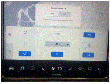
- Test A/C functions in vehicle to ensure cabin cooling functions as designed
 Courtesy of TESLA, INC. Courtesy of TESLA, INC.
|
- Perform A/C hose flush
NOTE:
Touch time only. No overlap from this since the machine is disconnected from the vehicle.
 Courtesy of TESLA, INC. Courtesy of TESLA, INC.
|
- Install under hood aprons
NOTE:
4x aprons
 Courtesy of TESLA, INC. Courtesy of TESLA, INC.
|
- Close hood
 Courtesy of TESLA, INC. Courtesy of TESLA, INC.
|
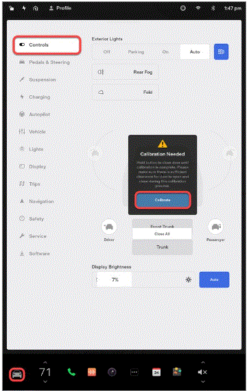
- Calibrate falcon doors via UI
NOTE:
Via Controls > Calibrate, Required after 12V and FRL disconnect
 Courtesy of TESLA, INC. Courtesy of TESLA, INC.
|
- Remove the steering wheel holder from the vehicle
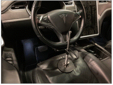 Courtesy of TESLA, INC. Courtesy of TESLA, INC.
|
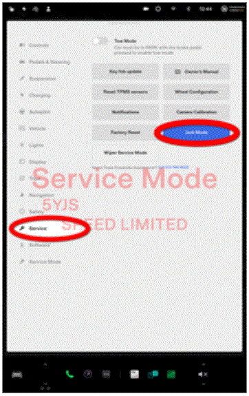
- Remove vehicle from lift
NOTE:
Lower rack arms fully and move them from under vehicle, Remove air suspension from "Jack Mode", Via Controls > Service > Jack Mode
 Courtesy of TESLA, INC. Courtesy of TESLA, INC.
|
 Courtesy of TESLA, INC. Courtesy of TESLA, INC.
|
- Close LH front door
 Courtesy of TESLA, INC. Courtesy of TESLA, INC.
|
- Review wheel alignment requirements and add correction code as needed
 Courtesy of TESLA, INC. Courtesy of TESLA, INC.
|