- Attach the drive unit sling tool to the new rear drive unit.
- Raise the new rear drive unit out of the crate.
- Move the new rear drive unit over the rear subframe.
- With an assistant, lower the drive unit sling tool to install the new rear drive unit into the rear subframe.
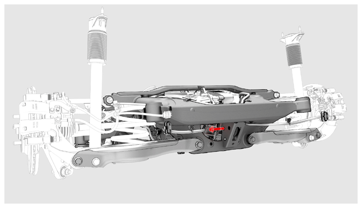
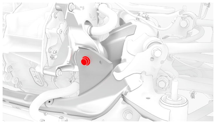
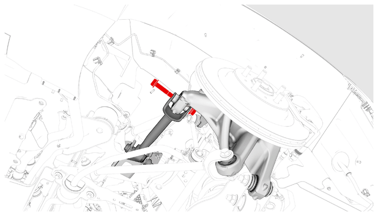
- Install and hand-tighten the bolt and nut that attach the rear bushing of the rear drive unit to the rear subframe.
 Courtesy of TESLA, INC. Courtesy of TESLA, INC.
|
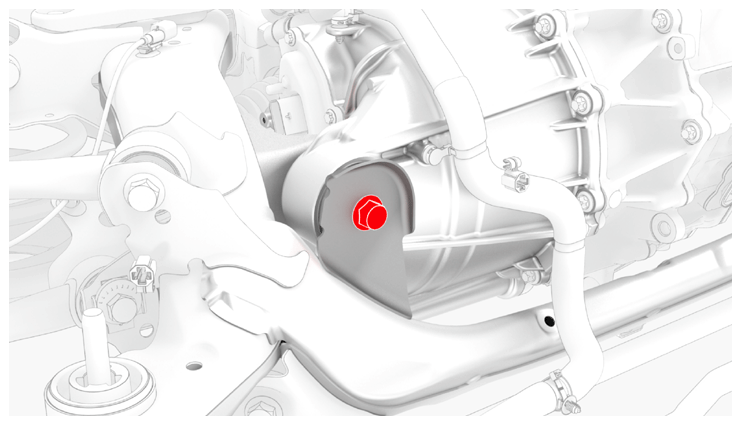
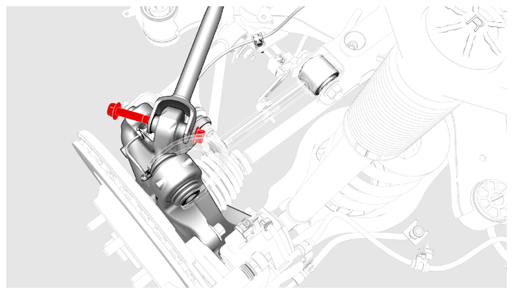
- Install and hand-tighten the bolt and nut that attach the RH bushing of the rear drive unit to the rear subframe.
 Courtesy of TESLA, INC. Courtesy of TESLA, INC.
|
 Courtesy of TESLA, INC. Courtesy of TESLA, INC.
|
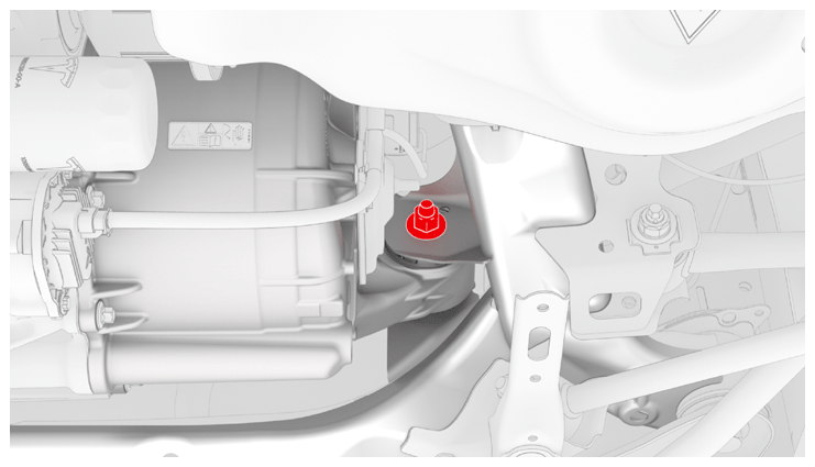
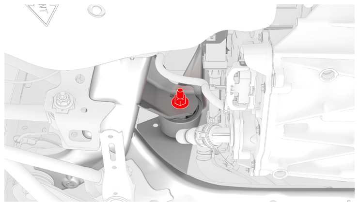
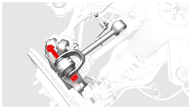
- Install and hand-tighten the bolt and nut that attach the LH mount of the rear drive unit to the rear subframe.
 Courtesy of TESLA, INC. Courtesy of TESLA, INC.
|
 Courtesy of TESLA, INC. Courtesy of TESLA, INC.
|
- Lower the drive unit sling tool to release the tension on the cables.
- Remove the drive unit sling tool from the gantry.
- Remove the drive unit sling tool from the rear drive unit.
- Tighten the LH mount, RH bushing, and rear bushing bolts and nuts that attach the rear drive unit to the rear subframe.
 80 N.m (59.0 ft-lbs)
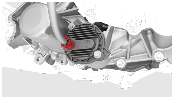
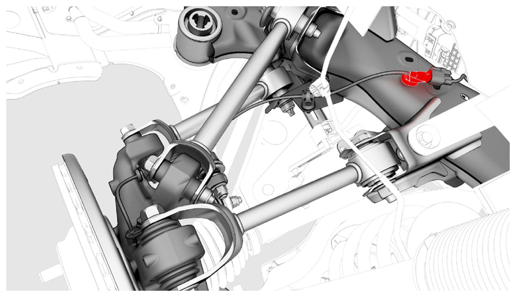
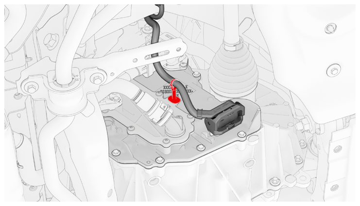
- Connect the electrical harness to the oil pump connector.
 Courtesy of TESLA, INC. Courtesy of TESLA, INC.
|
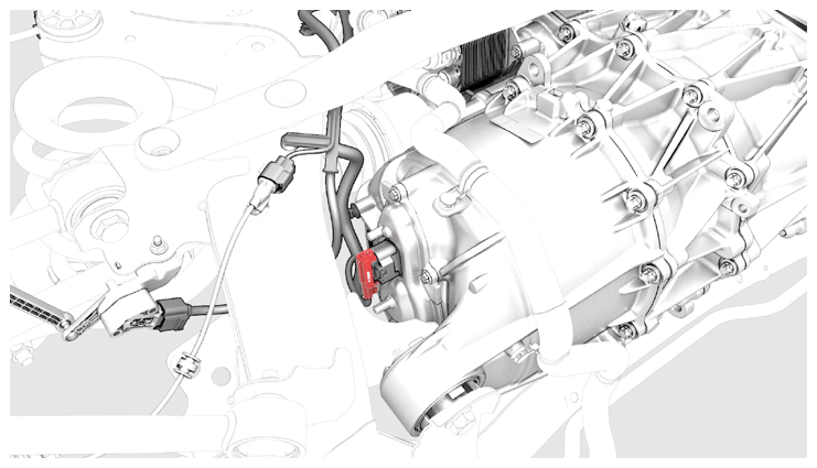
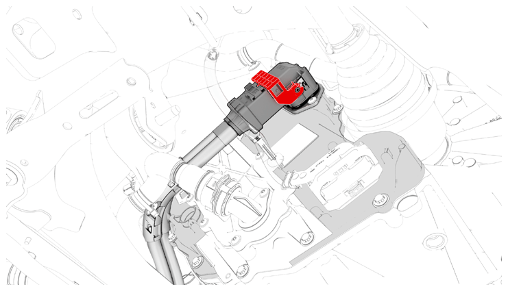
- Connect the electrical harness to the resolver connector.
 Courtesy of TESLA, INC. Courtesy of TESLA, INC.
|
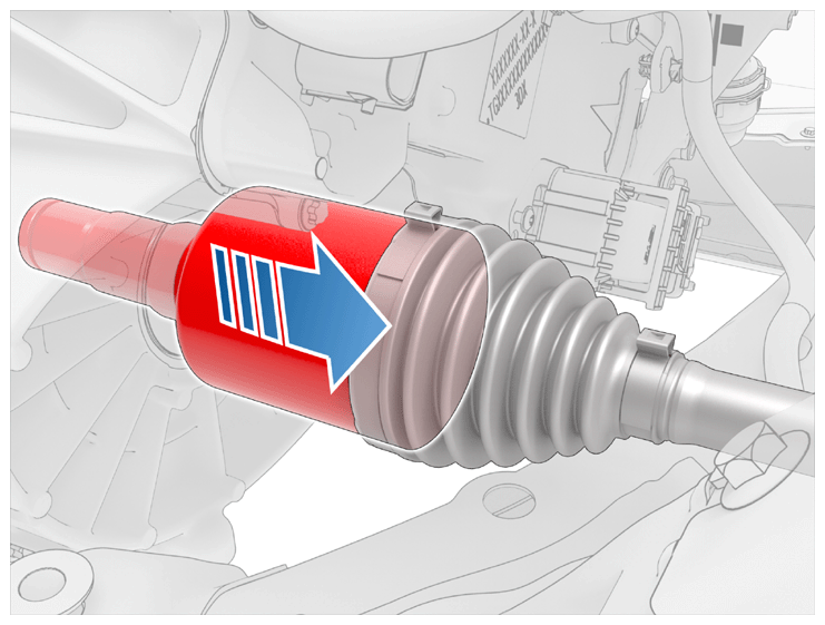
- Remove the LH halfshaft plug from the gearbox, and then with assistance, install the LH rear drive unit halfshaft into the rear drive unit.
CAUTION:
Take care not to damage or displace the oil seal.
CAUTION:
Make sure that the opening of the snap ring is facing towards the bottom of the drive unit.
NOTE:
Move the rear knuckle assembly aside to provide enough clearance to safely install the rear drive unit halfshaft.
NOTE:
New rear drive units come prefilled with gearbox fluid. Clean up any leaks during installation and top off the gearbox fluid as necessary. For more information, search for 1446276-00-B in the Service Tooling Catalog.
- Verify that the halfshaft is fully seated:
- Carefully push the halfshaft into the drive unit until there is an audible "click" from the halfshaft stub contacting the pinion shaft.
- There will be a slight pulling sensation on the halfshaft as the halfshaft circlip locks into place.
- Pull on the inner halfshaft cup to confirm that the circlip is locked into place. If the halfshaft detaches from the drive unit then reinstall the halfshaft and then test that it is fully seated.
 Courtesy of TESLA, INC. Courtesy of TESLA, INC.
|
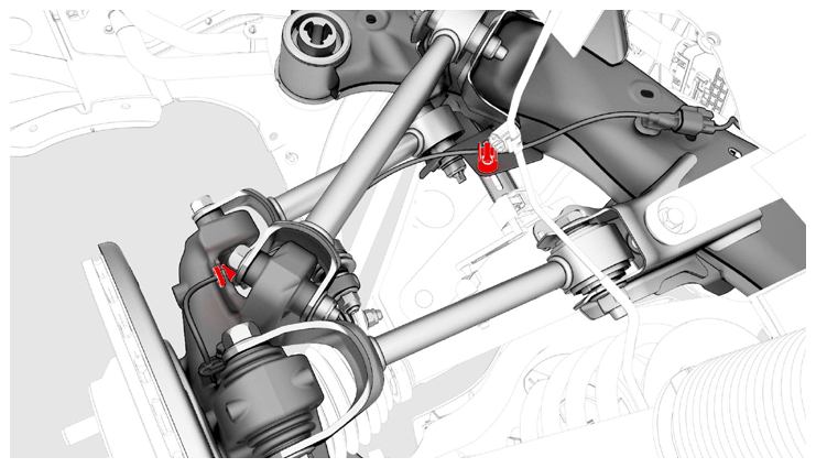
- Install the LH halfshaft to the hub and knuckle assembly.
- With an assistant, hand-tighten the bolt and nut that attach the LH toe link to the knuckle.
NOTE:
The bolt and nut will be tightened to specification during the Four Wheel Alignment (Check and Adjust) at the end of the Rear Subframe Assembly (Remove and Install) procedure.
 Courtesy of TESLA, INC. Courtesy of TESLA, INC.
|
- With an assistant, hand-tighten the bolt and nut that attach LH upper fore link to the knuckle.
NOTE:
The bolt and nut will be tightened to specification during the Four Wheel Alignment (Check and Adjust) at the end of the Rear Subframe Assembly (Remove and Install) procedure.
 Courtesy of TESLA, INC. Courtesy of TESLA, INC.
|
- With an assistant, hand-tighten the bolt and nut that attach the upper aft link to the knuckle.
NOTE:
The bolt and nut will be tightened to specification during the Four Wheel Alignment (Check and Adjust) at the end of the Rear Subframe Assembly (Remove and Install) procedure.
 Courtesy of TESLA, INC. Courtesy of TESLA, INC.
|
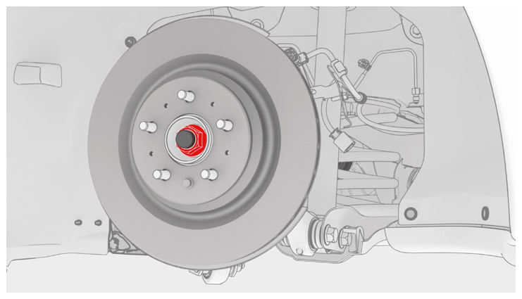
- Install the washer, and install a new nut to attach the halfshaft to the LH rear hub.
 300 N.m (221.2 ft-lbs)
 Courtesy of TESLA, INC. Courtesy of TESLA, INC.
|
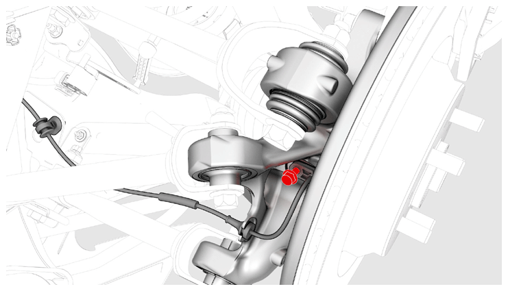
- Install the rear LH ABS wheel speed sensor to the knuckle, and then install a new bolt to attach the sensor to the knuckle.
 5 N.m (3.7 ft-lbs)
 Courtesy of TESLA, INC. Courtesy of TESLA, INC.
|
- Fasten the clip and install the grommet that attach the rear LH ABS wheel speed sensor cable to the rear LH knuckle and bracket.
CAUTION:
Perform a push-pull check on the clip and grommet to make sure they are securely fastened to the knuckle and bracket.
 Courtesy of TESLA, INC. Courtesy of TESLA, INC.
|
- Connect the subframe harness to the rear LH ABS wheel speed sensor connector, and then fasten the clip that attaches the connector to the rear subframe.
 Courtesy of TESLA, INC. Courtesy of TESLA, INC.
|
- Repeat step 14 through 23 on the RH side of the rear drive unit.
- Fully raise the handle on the rear drive unit HV connector of the rear drive unit to HV battery harness.
 Courtesy of TESLA, INC. Courtesy of TESLA, INC.
|
- Install the HV connector special tool onto the rear drive unit HV connector.
 Courtesy of TESLA, INC. Courtesy of TESLA, INC.
|
- Use both hands to firmly connect the rear drive unit HV connector of the rear drive unit to HV battery harness to the rear drive unit HV header.
CAUTION:
Make sure that the connector fits the header squarely and tightly, and that both retention pins enter the handle.
- Remove the HV connector special tool from the rear drive unit HV connector.
- While pressing the rear drive unit HV connector onto the rear drive unit HV header, fully lower the handle.
CAUTION:
Make sure that the handle does not bind as it is lowered.
 Courtesy of TESLA, INC. Courtesy of TESLA, INC.
|
- Slide the release to lock the rear drive unit HV connector handle in the secured position.
 Courtesy of TESLA, INC. Courtesy of TESLA, INC.
|
- Verify that the rear drive unit HV connector is fully seated, and compare both sides of the connector that it is properly secured in place.
NOTE:
An improperly seated connector might lead to connector damage and rear drive unit problems later on.
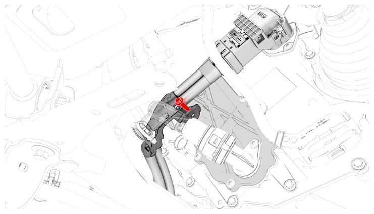
- Install the bolt that attaches the HV harness bracket to the inverter.
 6 N.m (4.4 ft-lbs)
 Courtesy of TESLA, INC. Courtesy of TESLA, INC.
|
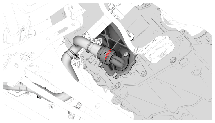
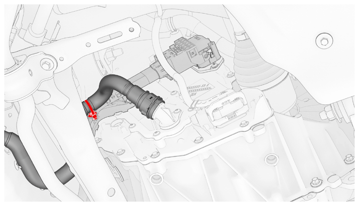
- Connect the rear drive unit inlet hose to the inverter coolant inlet, and then fasten the clip.
CAUTION:
Perform a push-pull test to verify that the hose is fully seated.
 Courtesy of TESLA, INC. Courtesy of TESLA, INC.
|
- Fasten the clip that attaches the rear drive unit inlet hose to the HV harness bracket.
 Courtesy of TESLA, INC. Courtesy of TESLA, INC.
|
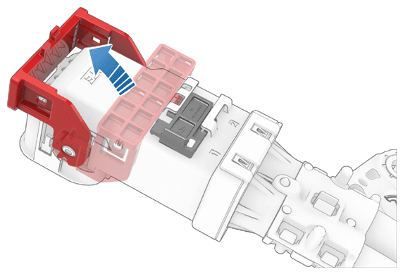
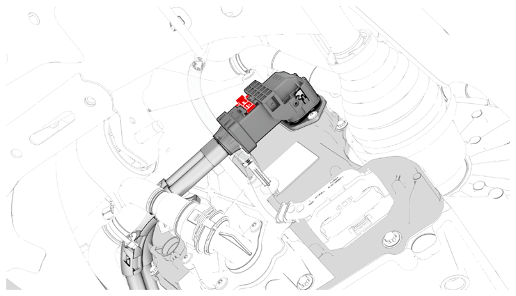
- Connect the electrical harness to the inverter low voltage connector.
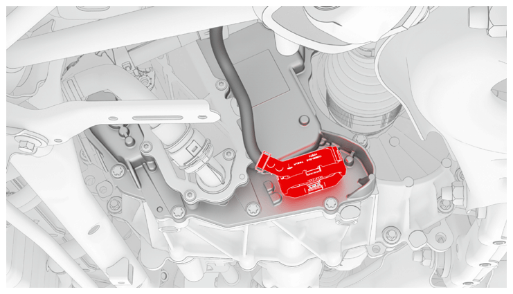 Courtesy of TESLA, INC. Courtesy of TESLA, INC.
|
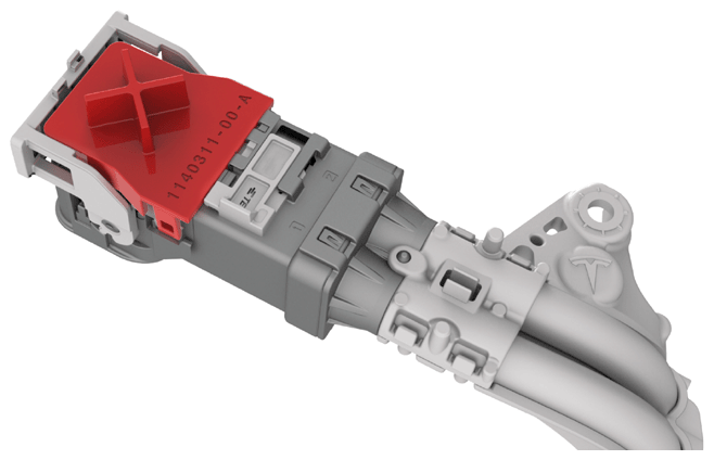
- Fasten the clip that attaches the low voltage electrical harness to the inverter.
 Courtesy of TESLA, INC. Courtesy of TESLA, INC.
|
- Install the rear subframe assembly. See SUBFRAME ASSEMBLY - REAR (REMOVE AND INSTALL)
.
- Check the vehicle wheel alignment, and adjust if necessary. See FOUR WHEEL ALIGNMENT CHECK
.