- Put the front subframe assembly with the powertrain table/subframe fixture under the vehicle for installation.
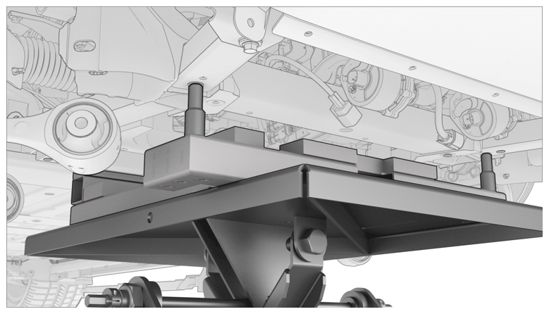
- Raise the front subframe assembly into position to be installed.
CAUTION:
Do not work on the front subframe assembly while it is under the vehicle.
CAUTION:
Do not damage the front end carrier while the front subframe assembly is raised to the vehicle. The powertrain table must be tilted on the rear side angle down, and the front side tilted up as the front subframe is clearing the front end carrier.
 Courtesy of TESLA, INC. Courtesy of TESLA, INC.
|
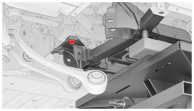
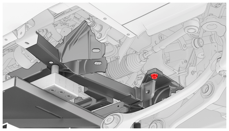
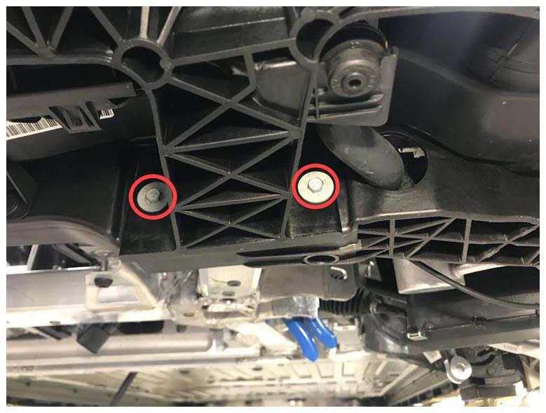
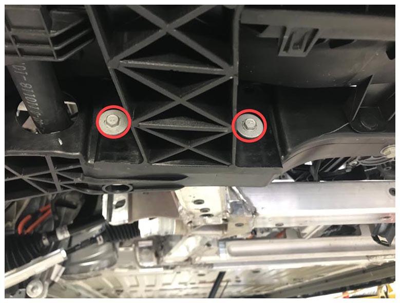
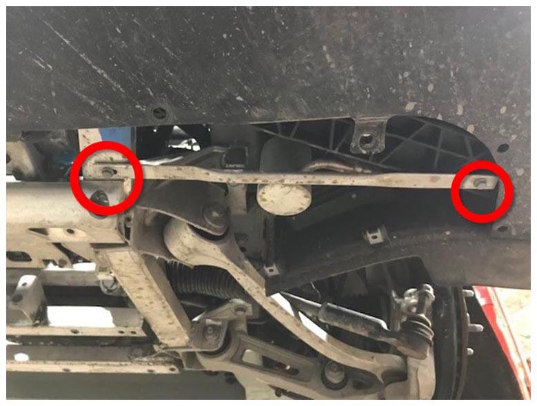
- Install the RH rear bolt that attaches the front subframe assembly to the body (torque 115 N.m). Repeat this step on the LH rear bolt.
NOTE:
RH side
 Courtesy of TESLA, INC. Courtesy of TESLA, INC.
|
NOTE:
LH side
 Courtesy of TESLA, INC. Courtesy of TESLA, INC.
|
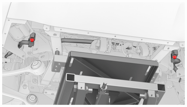
- Install the bolt that attaches the RH stabilizer bar mount to the body through the front subframe assembly (torque 80 N.m). Repeat this step on the LH stabilizer bar mount.
 Courtesy of TESLA, INC. Courtesy of TESLA, INC.
|
- Install new bolts (x4) that attach the bumper carrier to the front subframe assembly (torque 7.5 N.m).
NOTE:
LH side
 Courtesy of TESLA, INC. Courtesy of TESLA, INC.
|
NOTE:
RH side
 Courtesy of TESLA, INC. Courtesy of TESLA, INC.
|
- Lower the powertrain table, and then remove it from under the vehicle.
- Disconnect the shop air supply from the powertrain table.
- Put the coolant drain container under the LH front corner of the vehicle to catch any coolant during the next step.
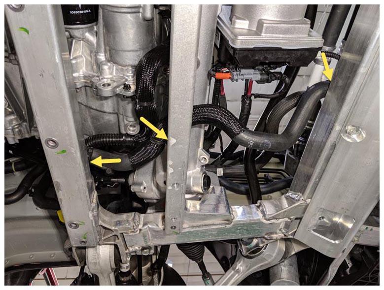
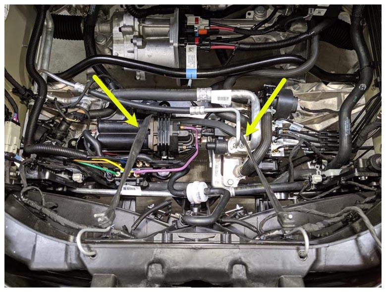
- Install the fir tree clips (x3) that attach the battery coolant heater-to-coolant pump 2 between the steering rack and the front subframe.
 Courtesy of TESLA, INC. Courtesy of TESLA, INC.
|
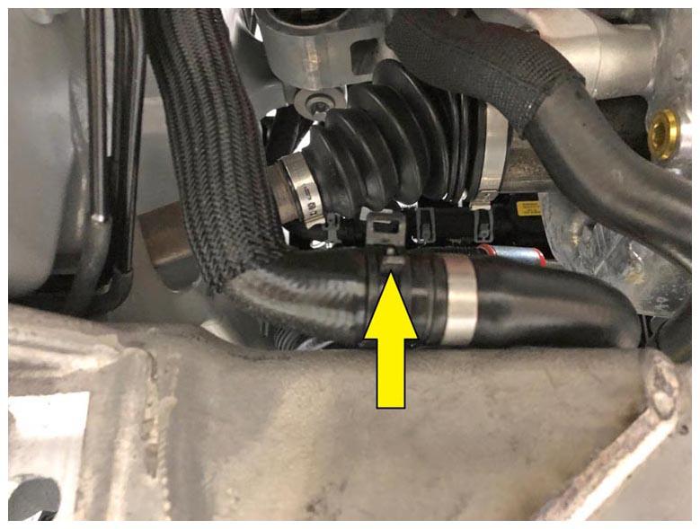
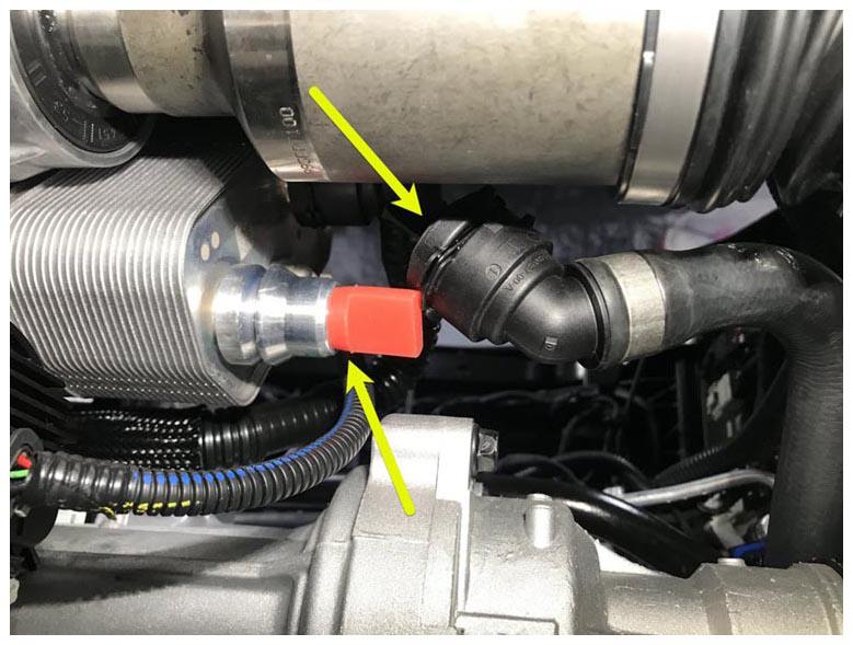
- Remove the hose plugs, and then install the battery coolant heater-to-coolant pump 2 hose at the rear of the front subframe assembly and secure it with the hose clamp.
 Courtesy of TESLA, INC. Courtesy of TESLA, INC.
|
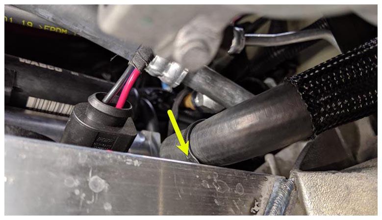
- Remove the hose plug, and then secure the hose clip and the fir tree clip that attach the coolant hose to the radiator inlet.
 Courtesy of TESLA, INC. Courtesy of TESLA, INC.
|
 Courtesy of TESLA, INC. Courtesy of TESLA, INC.
|
- Remove the coolant drain container from under the vehicle.
- Slide the lower i-shaft onto the steering rack, and then install the bolt that attaches the lower i-shaft to the steering rack (torque 30 N.m).
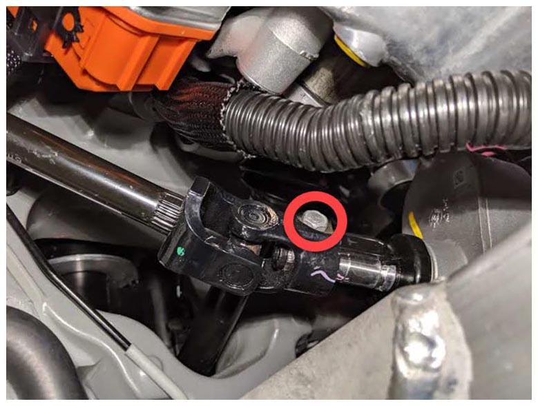 Courtesy of TESLA, INC. Courtesy of TESLA, INC.
|
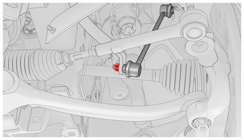
- Install a new nut that attaches the RH stabilizer bar to the stabilizer bar end link (torque 70 N.m). Repeat this step on the LH stabilizer bar.
NOTE:
LH shown, RH similar
 Courtesy of TESLA, INC. Courtesy of TESLA, INC.
|
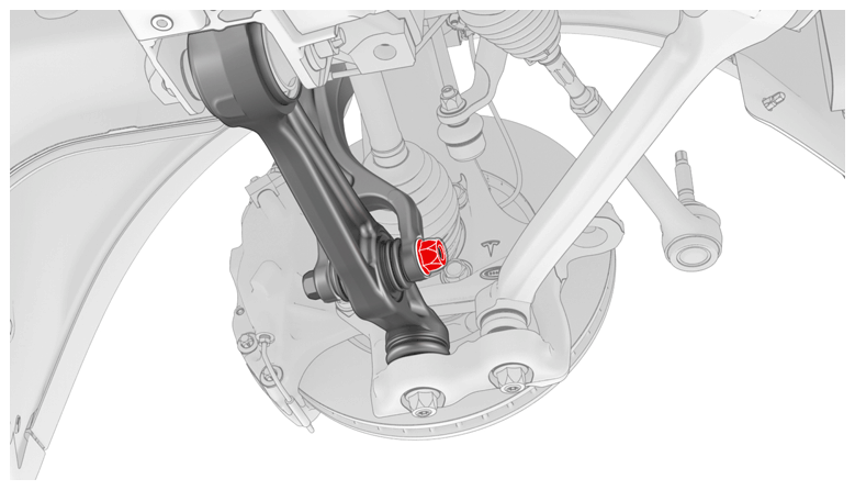
- Move the RH front fore link into the front subframe assembly, properly align the paint marks, and then hand-tighten the bolt that attaches the RH front lower fore link to the subframe.
NOTE:
The bolt will be fully tightened during wheel alignment later in this procedure (torque specification for the bolt is 130 N.m).
 Courtesy of TESLA, INC. Courtesy of TESLA, INC.
|
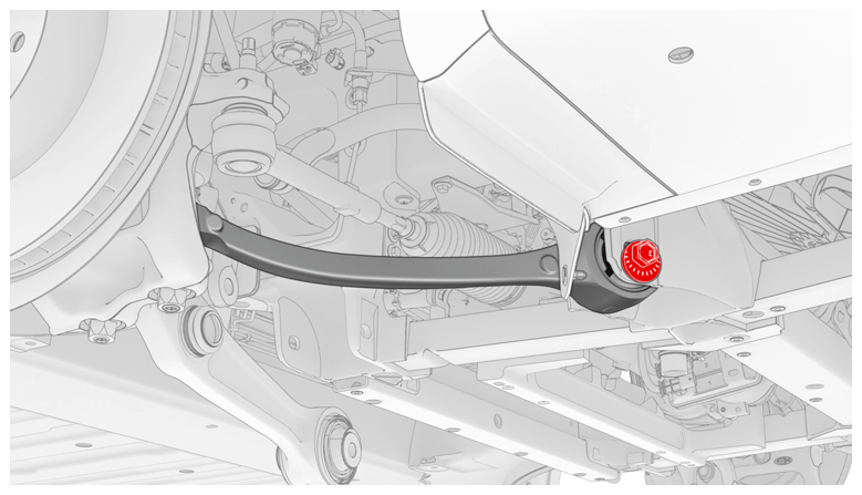
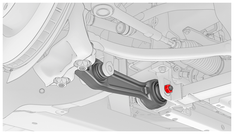
- Move the RH front lower aft link into position on the front subframe assembly, and then hand-tighten the bolt.
NOTE:
Make sure that the bolt is installed with the bolt head facing the front of the vehicle.
NOTE:
The bolt will be fully tightened during wheel alignment later in this procedure (torque specification for the bolt is 130 N.m).
 Courtesy of TESLA, INC. Courtesy of TESLA, INC.
|
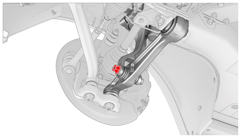
- Move the LH front lower fore link into the front subframe assembly, properly align the paint marks, and then hand-tighten the bolt that attaches the link to the subframe.
NOTE:
The bolt will be fully tightened during wheel alignment later in this procedure (torque specification for the bolt is 130 N.m).
 Courtesy of TESLA, INC. Courtesy of TESLA, INC.
|
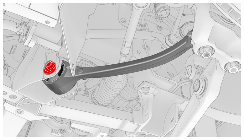
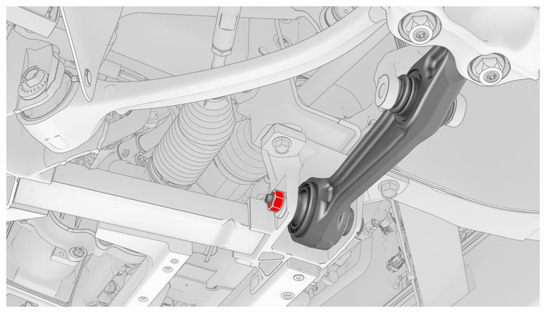
- Move the LH front lower aft link into position on the front subframe assembly, and then hand-tighten the bolt that attaches the link to the subframe.
NOTE:
Make sure that the bolt is installed with the bolt head facing the front of the vehicle.
NOTE:
The bolt will be fully tightened during wheel alignment later in this procedure (torque specification for the bolt is 130 N.m).
 Courtesy of TESLA, INC. Courtesy of TESLA, INC.
|
- Install the bolt that attaches the LH front strut to the front lower aft link. Repeat this step on the RH front strut.
NOTE:
Torque the bolts at ride height when the vehicle is on the alignment rack later in this procedure (torque specification for the bolt is 140 N.m).
NOTE:
LH side
 Courtesy of TESLA, INC. Courtesy of TESLA, INC.
|
NOTE:
RH side
 Courtesy of TESLA, INC. Courtesy of TESLA, INC.
|
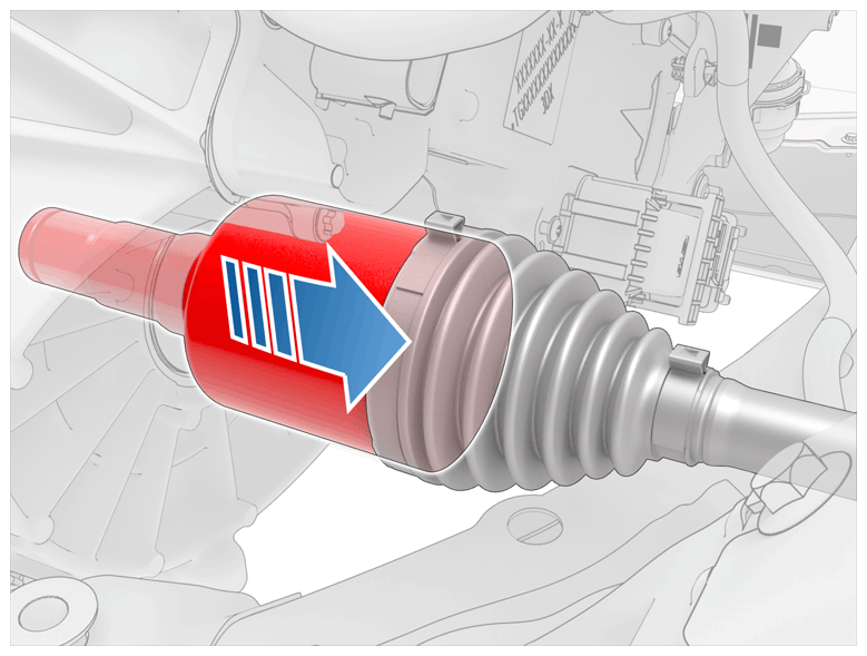
- Pull on the LH and RH front inner halfshaft cups to confirm that the circlip is locked into place. If the halfshaft detaches from the drive unit then reinstall the halfshaft and then test that it is fully seated.
CAUTION:
If reinstalling the halfshaft to the drive unit:
- Take care not to damage or displace the oil seals.
- Make sure that the opening of the snap rings are facing towards the bottom of the drive unit.
- Carefully push the halfshaft into the drive unit until there is an audible "click" from the halfshaft stub contacting the pinion shaft.
- There will be a slight pulling sensation on the halfshaft as the halfshaft circlip locks into place.
- Pull on the inner halfshaft cup to confirm that the circlip is locked into place. If the halfshaft detaches from the drive unit then reinstall the halfshaft and then test that it is fully seated.
 Courtesy of TESLA, INC. Courtesy of TESLA, INC.
|
- Install the front subframe skid bar. See SKID BAR - FRONT SUBFRAME (REMOVE AND REPLACE) .
- Install the front skidplate. See SKIDPLATE - FRONT (REMOVE AND REPLACE) .
- Install the front bash plate stamping. See BASH PLATE - FRONT - STAMPING (REMOVE AND REPLACE) .
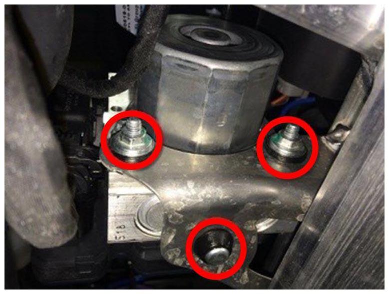
- Install the ABS pump onto the rubber mounting grommet, and then install the nuts (x2) that attach the ABS pump to the front subframe (torque 9 N.m).
 Courtesy of TESLA, INC. Courtesy of TESLA, INC.
|
- Install the bolts (x2) that attach the LH stay bar to the front subframe assembly (torque 11 N.m). Repeat this step on the RH stay bar.
 Courtesy of TESLA, INC. Courtesy of TESLA, INC.
|
- Install the front aero shield panel. See Panel - Aero Shield - Front (Remove and Replace)
.
- Install the HV battery assembly. See HV Battery (RWD/AWD) (Remove and Install)
.
- Install the front extrusion bash plate. See BASH PLATE - FRONT - EXTRUSION (REMOVE AND REPLACE) .
- Install the mid aero shield panel. See Panel - Aero Shield - Mid (Remove and Replace)
.
- Lower the vehicle partially.
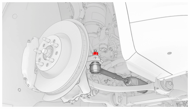
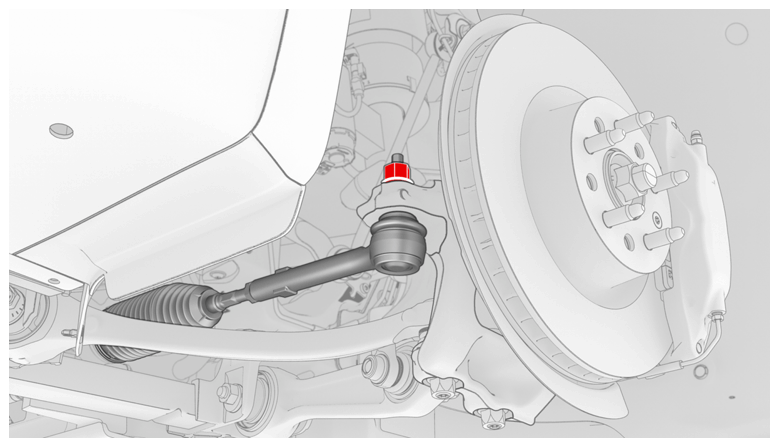
- Install the LH tie rod end into the knuckle, and then install a new LH nyloc nut that attaches the tie rod end to the steering knuckle (torque 103 N.m). Repeat this step on the RH tie rod end.
NOTE:
RH side
 Courtesy of TESLA, INC. Courtesy of TESLA, INC.
|
NOTE:
LH side
 Courtesy of TESLA, INC. Courtesy of TESLA, INC.
|
- Install the LH and RH front wheels. See Wheel (Remove and Install)
.
NOTE:
Before installing the LH and RH front wheel center caps, tighten the LH and RH front axle nuts (torque 245 N.m).
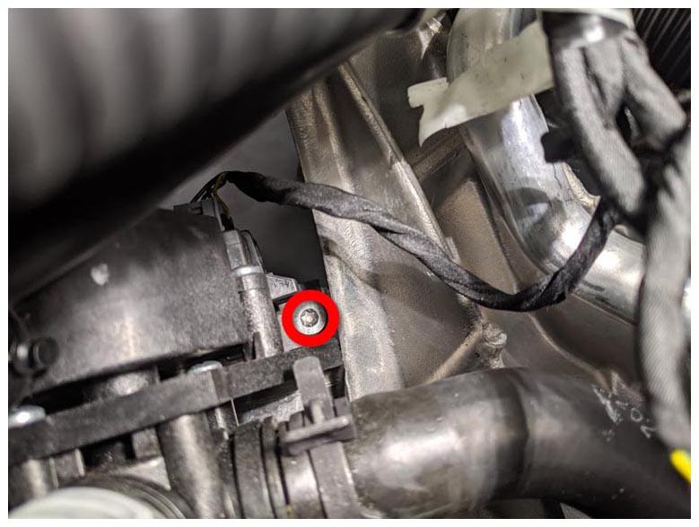
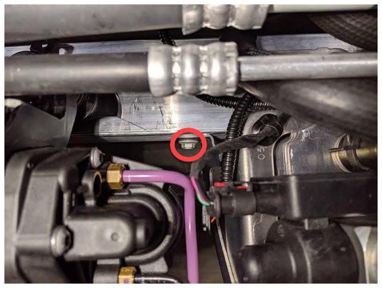
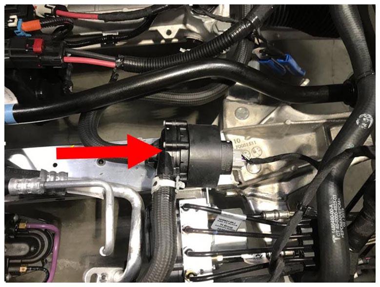
- Tighten the bolt that attaches the 3-way valve to the front subframe assembly (torque 5 N.m).
 Courtesy of TESLA, INC. Courtesy of TESLA, INC.
|
- Release the air suspension pump bracket and chiller assembly from the front end carrier.
 Courtesy of TESLA, INC. Courtesy of TESLA, INC.
|
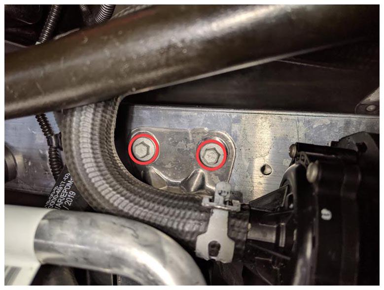
- Install the bolts (x2) that attach the air suspension pump bracket to the front subframe assembly (torque 5.5 N.m).
 Courtesy of TESLA, INC. Courtesy of TESLA, INC.
|
- Install the bolts (x3) that attach the chiller assembly to the front subframe assembly (torque 5 N.m).
 Courtesy of TESLA, INC. Courtesy of TESLA, INC.
|
 Courtesy of TESLA, INC. Courtesy of TESLA, INC.
|
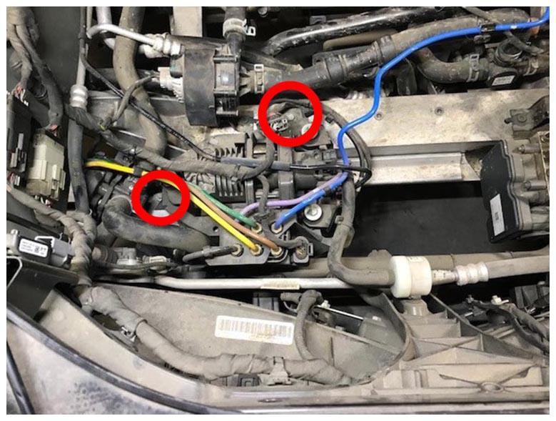
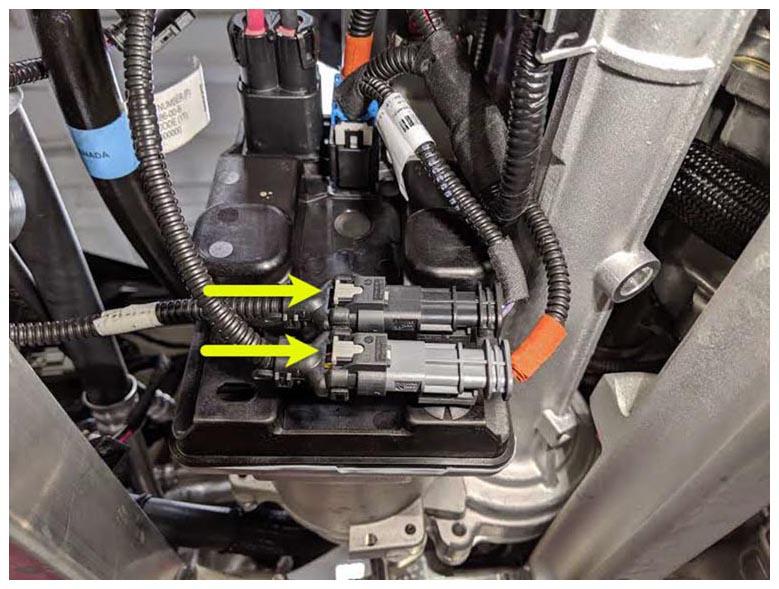
- Connect the electrical connectors (x2) for the steering rack logic.
NOTE:
Engage the gray locks after the electrical connectors are fully seated.
 Courtesy of TESLA, INC. Courtesy of TESLA, INC.
|
- Install the clip that attaches the logic harness connector to the front subframe assembly.
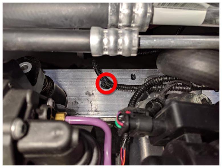 Courtesy of TESLA, INC. Courtesy of TESLA, INC.
|
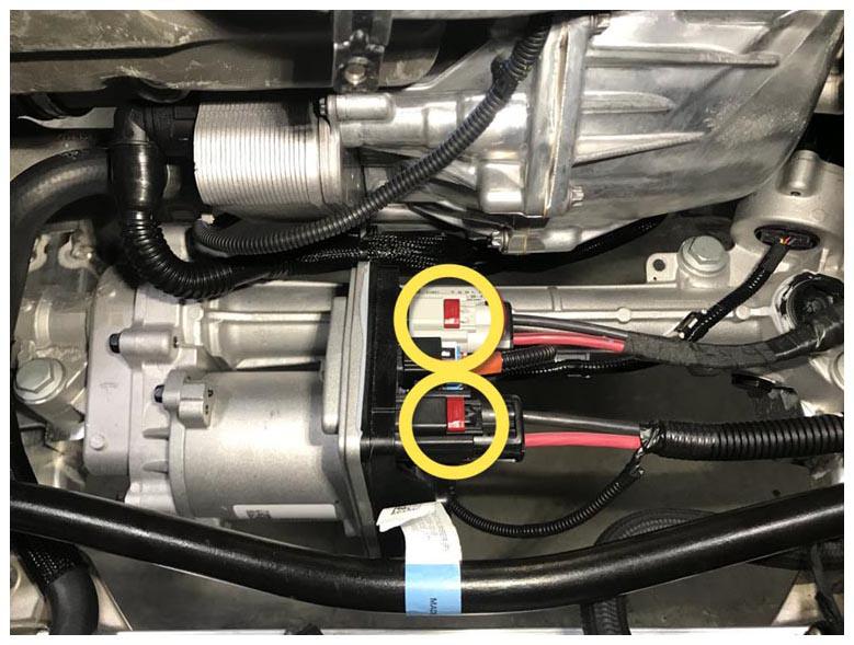
- Connect the steering rack electrical connectors (x2).
NOTE:
Make sure that the red locking tab is engaged after hearing an audible click when connecting the steering rack connectors.
 Courtesy of TESLA, INC. Courtesy of TESLA, INC.
|
- Remove the plugs from both the coolant hose from the 4-way valve and the battery pump 2, immediately connect the hose to the pump, and then fasten the hose clamp that attaches the hose to the pump.
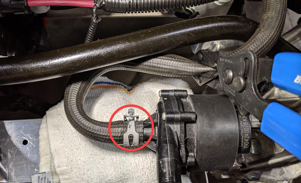 Courtesy of TESLA, INC. Courtesy of TESLA, INC.
|
- Remove the absorbent material from under the battery pump 2.
- Slide the battery pump 2 onto the mounting bracket at the front subframe assembly.
 Courtesy of TESLA, INC. Courtesy of TESLA, INC.
|
- Reconnect 12V power. See Disconnect 12V Power
.
- Install the underhood storage unit. See Underhood Storage Unit (Remove and Install)
.
- Install the underhood storage carpet. See Carpet - Underhood Storage (Remove and Install)
.
- Install the rear underhood apron. See Underhood Apron - Rear (Remove and Replace)
.
- Install the HEPA filter outlet duct. See Duct - HEPA Filter - Outlet (Remove and Replace)
.
- Install the HEPA filter inlet duct. See Duct - HEPA Filter - Inlet (Remove and Replace)
.
- Install the LH and RH underhood aprons. See Underhood Apron - LH (Remove and Replace)
.
- Connect a laptop with Toolbox to the vehicle.
- In Toolbox, click Panels > Thermal > Coolant Air Purge
.
- Top off the coolant reservoir and reinstall the coolant bottle cap, if necessary.
- Install the mid aero shield. See Panel - Aero Shield - Mid (Remove and Replace)
.
- Close the hood.
- Disconnect the laptop from the vehicle and reinstall the storage cubby.
- Position the front passenger seat back to its original position.
- Remove the steering wheel holder from the vehicle.
- Refer to the Alignment Requirement tables to determine if an alignment check (AC) or full adjustment (FA) is necessary. See Alignment Requirement - Suspension
.
NOTE:
Make sure that the front fore links, front lower fore links, and the front lower aft links are tightened to specifications during this procedure.
- Install the mid aero shield panel.
- Remove the brake pedal depressor, the steering wheel level, the steering wheel holder from the vehicle, and then shift into Park.
- Remove the wheel chocks, and then remove the vehicle from the 4-post lift.
- Perform a vehicle test drive.