| 1 |
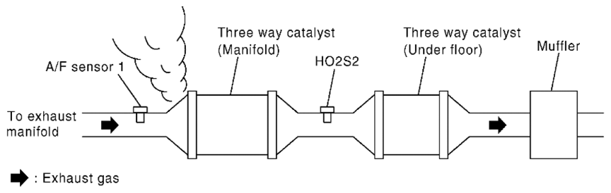
CHECK EXHAUST GAS LEAK
- Start engine and run it at idle.
- Listen for an exhaust gas leak before three way catalyst (manifold).
 Courtesy of SUZUKI OF AMERICA CORP. Courtesy of SUZUKI OF AMERICA CORP.
OK or NG |
GO TO 2. |
Repair or replace. |
| 2 |
CHECK FOR INTAKE AIR LEAK
- Listen for an intake air leak after the mass air flow sensor.
- Check PCV hose connection.
OK or NG |
GO TO 3. |
Repair or replace. |
| 3 |
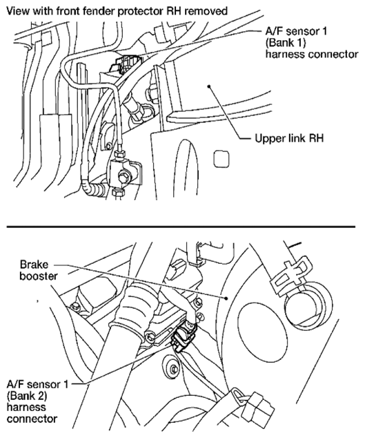
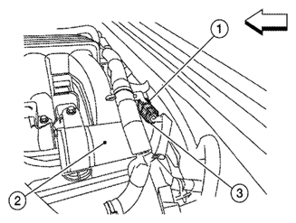
CHECK A/F SENSOR 1 INPUT SIGNAL CIRCUIT
- Turn ignition switch OFF.
- Disconnect corresponding A/F sensor 1 harness connector.
   Courtesy of SUZUKI OF AMERICA CORP.SUZUKI OF AMERICA CORP.SUZUKI OF AMERICA CORP. Courtesy of SUZUKI OF AMERICA CORP.SUZUKI OF AMERICA CORP.SUZUKI OF AMERICA CORP.
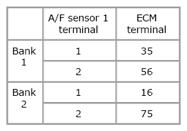
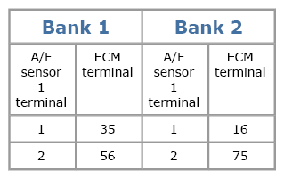
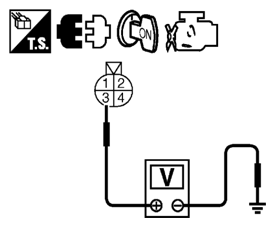
- 3. Disconnect ECM harness connector.
- 4. Check harness continuity between A/F sensor 1 terminal and ECM terminal as follows.
Refer to WIRING DIAGRAM
.
Courtesy of SUZUKI OF AMERICA CORP.SUZUKI OF AMERICA CORP.SUZUKI OF AMERICA CORP.
Continuity should exist.
- 5. Check harness continuity between the following terminals and ground. Refer to WIRING DIAGRAM
.
Courtesy of SUZUKI OF AMERICA CORP.SUZUKI OF AMERICA CORP.SUZUKI OF AMERICA CORP.
Continuity should not exist.
- 6. Also check harness for short to power.
OK or NG |
GO TO 4. |
Repair open circuit or short to ground or short to power in harness or connectors. |
| 4 |
CHECK FUEL PRESSURE
- Release fuel pressure to zero. Refer to
[FUEL PRESSURE CHECK: VQ40DE
]
- Install fuel pressure gauge and check fuel pressure. Refer to
[FUEL PRESSURE CHECK: VQ40DE
]
At idling: 350 kPa (3.57 kg/cm 2
, 51 psi)
OK or NG |
GO TO 6. |
GO TO 7. |
| 5 |
DETECT MALFUNCTIONING PART
Check the following.
|
Repair or replace. |
|
| 6 |
CHECK MASS AIR FLOW SENSOR
With SDT
- Install all removed parts.
- Check "MASS AIR FLOW" in "Data list" mode with SDT.
2.0 - 6.0 g/sec: at idling
7.0 - 20.0 g/sec: at 2, 500 RPM
OK or NG |
GO TO 8. |
Check connectors for rusted terminals or loose connections in the mass air flow sensor circuit or ground. Refer to
[P0101 MAF SENSOR ]. |
| 7 |
CHECK MASS AIR FLOW SENSOR
With GST
- Install all removed parts.
- Check mass air flow sensor signal in Service $01 with GST.
2.0 - 6.0 g/sec: at idling
7.0 - 20.0 g/sec: at 2, 500 RPM
OK or NG |
GO TO 9. |
GO TO 11. |
| 8 |
CHECK FUNCTION OF FUEL INJECTOR
With SDT
- Start engine.
- Perform "POWER BALANCE" in "Active test" mode with SDT.
- Check that each circuit produces a momentary engine speed drop.
OK or NG |
GO TO 12. |
Perform trouble diagnosis for FUEL INJECTOR, refer to
[FUEL INJECTOR CIRCUIT CHECK
]. |
| 9 |
CHECK FUNCTION OF FUEL INJECTOR-I
Without SDT
- Stop engine.
- Disconnect harness connector F44 (3), F201 (1)
   Courtesy of SUZUKI OF AMERICA CORP.SUZUKI OF AMERICA CORP.SUZUKI OF AMERICA CORP. Courtesy of SUZUKI OF AMERICA CORP.SUZUKI OF AMERICA CORP.SUZUKI OF AMERICA CORP.
2: Vacuum tank
<==: Front
- 3. Turn ignition switch ON.
- 4. Check voltage between harness connector F44 terminal 3 and ground with SDT or tester.
Courtesy of SUZUKI OF AMERICA CORP.SUZUKI OF AMERICA CORP.SUZUKI OF AMERICA CORP.
Voltage: Battery voltage
- 5. Turn ignition switch OFF.
- 6. Disconnect ECM harness connector.
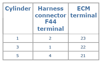
- 7. Check harness continuity between harness connector F44 and ECM as follows.
Refer to WIRING DIAGRAM
.
Courtesy of SUZUKI OF AMERICA CORP.SUZUKI OF AMERICA CORP.SUZUKI OF AMERICA CORP.
Continuity should exist.
- 8. Also check harness for short to ground and short to power.
OK or NG |
GO TO 10. |
Perform trouble diagnosis for FUEL INJECTOR, refer to
[FUEL INJECTOR CIRCUIT CHECK
]. |
| 10 |
CHECK FUNCTION OF FUEL INJECTOR-II
Provide battery voltage between harness connector F201 as follows and then interrupt it. Listen to each fuel injector operating sound.
Operating sound should exist.
OK or NG |
GO TO 12. |
Perform trouble diagnosis for FUEL INJECTOR, refer to
[FUEL INJECTOR CIRCUIT CHECK
]. |
| 11 |
CHECK FUNCTION OF FUEL INJECTOR
- Start engine.
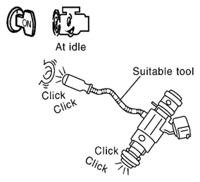 Courtesy of SUZUKI OF AMERICA CORP. Courtesy of SUZUKI OF AMERICA CORP.
- 2. Listen to fuel injectors No. 2, No. 4, No. 6 operating sound.
Clicking noise should exist.
OK or NG |
GO TO 12. |
Perform trouble diagnosis for FUEL INJECTOR, refer to
[FUEL INJECTOR CIRCUIT CHECK
]. |
| 12 |
CHECK FUEL INJECTOR
- Confirm that the engine is cooled down and there are no fire hazards near the vehicle.
- Turn ignition switch OFF.
- Disconnect all injector harness connectors.
- Remove fuel tube assembly. Refer to
[FUEL INJECTOR AND FUEL TUBE: REMOVAL AND INSTALLATION [VQ40DE]
]
Keep fuel hose and all fuel injectors connected to fuel tube.
- For DTC P0171, reconnect fuel injector harness connectors on bank 1.
For DTC P0174, reconnect fuel injector harness connectors on bank 2.
- Disconnect all ignition coil harness connectors.
- Prepare pans or saucers under each fuel injector.
- Crank engine for about 3 seconds.
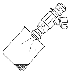 Courtesy of SUZUKI OF AMERICA CORP. Courtesy of SUZUKI OF AMERICA CORP.
For DTC P0171, check that fuel sprays out from fuel injectors on bank 1.
For DTC P0174, check that fuel sprays out from fuel injectors on bank 2.
Fuel should be sprayed evenly for each fuel injector.
OK or NG |
GO TO 13. |
Replace fuel injectors from which fuel does not spray out. Always replace O-ring with new ones. |
| 13 |
CHECK INTERMITTENT INCIDENT
Refer to
[SERVICE INFORMATION FOR ELECTRICAL INCIDENT: INTERMITTENT INCIDENT
] |
INSPECTION END |
|