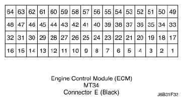
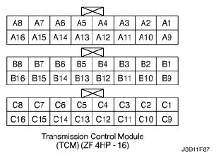
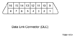
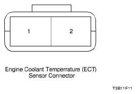
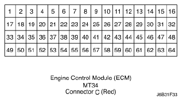
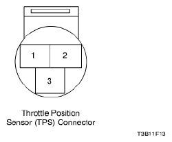
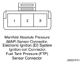
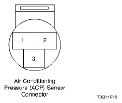
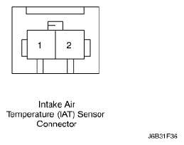
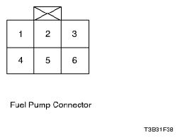
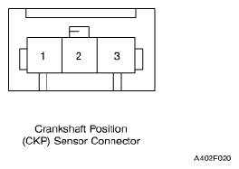
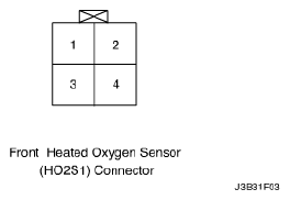
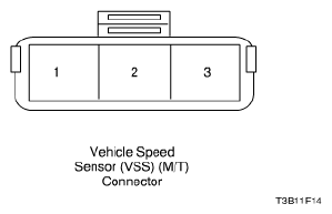
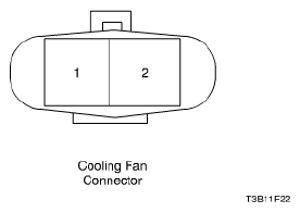
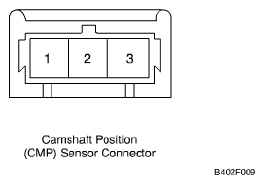
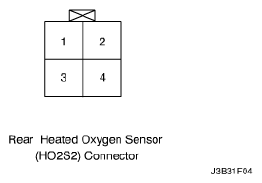
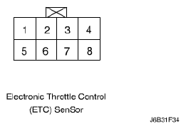
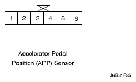
Connector End View Diagram
 Courtesy of SUZUKI OF AMERICA CORP.
 Courtesy of SUZUKI OF AMERICA CORP.
 Courtesy of SUZUKI OF AMERICA CORP.
 Courtesy of SUZUKI OF AMERICA CORP.
 Courtesy of SUZUKI OF AMERICA CORP.
 Courtesy of SUZUKI OF AMERICA CORP.
 Courtesy of SUZUKI OF AMERICA CORP.
 Courtesy of SUZUKI OF AMERICA CORP.
 Courtesy of SUZUKI OF AMERICA CORP.
 Courtesy of SUZUKI OF AMERICA CORP.
 Courtesy of SUZUKI OF AMERICA CORP.
 Courtesy of SUZUKI OF AMERICA CORP.
 Courtesy of SUZUKI OF AMERICA CORP.
 Courtesy of SUZUKI OF AMERICA CORP.
 Courtesy of SUZUKI OF AMERICA CORP.
 Courtesy of SUZUKI OF AMERICA CORP.
 Courtesy of SUZUKI OF AMERICA CORP.
 Courtesy of SUZUKI OF AMERICA CORP.
 Courtesy of SUZUKI OF AMERICA CORP.
 Courtesy of SUZUKI OF AMERICA CORP.
 Courtesy of SUZUKI OF AMERICA CORP.
 Courtesy of SUZUKI OF AMERICA CORP.