Check Power Supply And Ground Line Of Engine Control Module (ECM)
WARNING: This page is about a different variant/trim than selected.
CAUTION:
- After servicing or replacing faulty parts, perform Clear Memory Mode <Ref. to
OPERATION , Clear Memory Mode.>, and Inspection Mode <Ref. to
PROCEDURE , Inspection Mode.>.
- Use the check board when measuring the ECM terminal voltage and resistance.
WIRING DIAGRAM:
Engine Electrical System <Ref. to
WIRING DIAGRAM
, Engine Electrical System.>
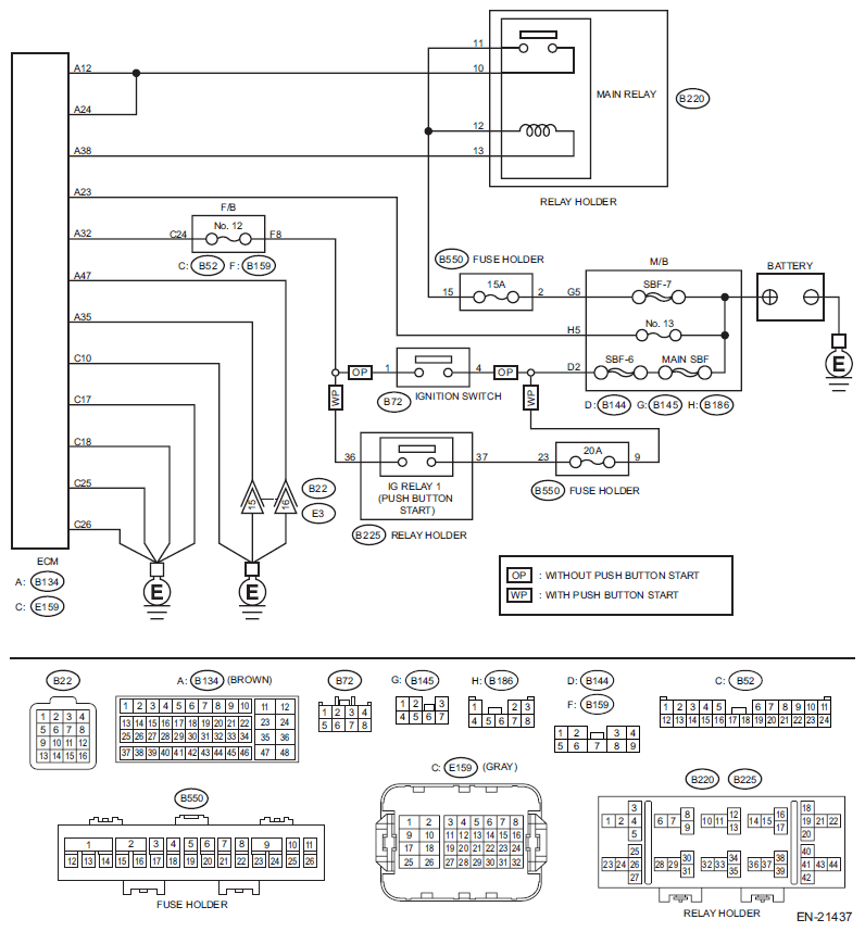 Courtesy of SUBARU OF AMERICA, INC.
| Step |
Check |
Yes |
No |
1 CHECK MAIN RELAY.
- Turn the ignition switch to OFF.
- Remove the main relay.
- Connect the battery to main relay terminals No. 12 and No. 13.
- Measure the resistance between main relay terminals.
Terminals
No. 10 - No. 11:
|
Is the resistance less than 1 Ω? |
Go to step 2
. |
Replace the main relay. <Ref. to
Main Relay
.> |
2 CHECK GROUND CIRCUIT FOR ECM.
- Disconnect the connector from ECM.
- Measure the resistance of harness between ECM connector and chassis ground.
Connector & terminal
(B134) No. 35 - Chassis ground:
(B134) No. 47 - Chassis ground:
(E159) No. 10 - Chassis ground:
(E159) No. 17 - Chassis ground:
(E159) No. 18 - Chassis ground:
(E159) No. 25 - Chassis ground:
(E159) No. 26 - Chassis ground:
|
Is the resistance less than 5 Ω? |
Go to step 3
. |
Repair the harness and connector.
NOTE:
In this case, repair the following item:
- Open circuit of harness between ECM connector and engine ground terminal
- Poor contact of coupling connector
|
3 CHECK INPUT VOLTAGE OF ECM.
- Turn the ignition switch to ON.
- Measure the voltage between ECM connector and chassis ground.
Connector & terminal
(B134) No. 23 (+) - Chassis ground (-):
(B134) No. 32 (+) - Chassis ground (-):
|
Is the voltage 10 V or more? |
Go to step 4
. |
Repair the open or ground short in the harness of power supply circuit. |
4 CHECK INPUT VOLTAGE OF MAIN RELAY.
Measure the voltage between main relay connector and chassis ground.
Connector & terminal
(B220) No. 11 (+) - Chassis ground (-):
(B220) No. 12 (+) - Chassis ground (-): |
Is the voltage 10 V or more? |
Go to step 5
. |
Repair the open or ground short in the harness of power supply circuit. |
5 CHECK INPUT VOLTAGE OF ECM.
- Turn the ignition switch to OFF.
- Install the main relay.
- Turn the ignition switch to ON.
- Measure the voltage between ECM connector and chassis ground.
Connector & terminal
(B134) No. 38 (+) - Chassis ground (-):
|
Is the voltage 10 V or more? |
Go to step 6
. |
Repair the open circuit of harness between ECM connector and main relay connector. |
6 CHECK INPUT VOLTAGE OF ECM.
- Turn the ignition switch to OFF.
- Connect the connector to ECM.
- Turn the ignition switch to ON.
- Measure the voltage between ECM connector and chassis ground.
Connector & terminal
(B134) No. 12 (+) - Chassis ground (-):
(B134) No. 24 (+) - Chassis ground (-):
|
Is the voltage 10 V or more? |
Check ignition control system. <Ref. to
IGNITION CONTROL SYSTEM , Diagnostics for Engine Starting Failure.> |
Repair the harness and connector.
NOTE:
In this case, repair the following item:
- Open circuit in harness between ECM connector and main relay connector
- Poor contact of main relay connector
- Poor contact of ECM connector
|