DTC P2530 Ignition Switch Run Position Circuit: Notes
DTC DETECTING CONDITION:
Immediately at fault recognition
TROUBLE SYMPTOM:
Improper idling
CAUTION:
- After servicing or replacing faulty parts, perform Clear Memory Mode <Ref. to
OPERATION
, Clear Memory Mode.>, and Inspection Mode <Ref. to
PROCEDURE
, Inspection Mode.>.
- Use the check board when measuring the ECM terminal voltage and resistance.
WIRING DIAGRAM:
Engine Electrical System <Ref. to
WIRING DIAGRAM
, Engine Electrical System.>
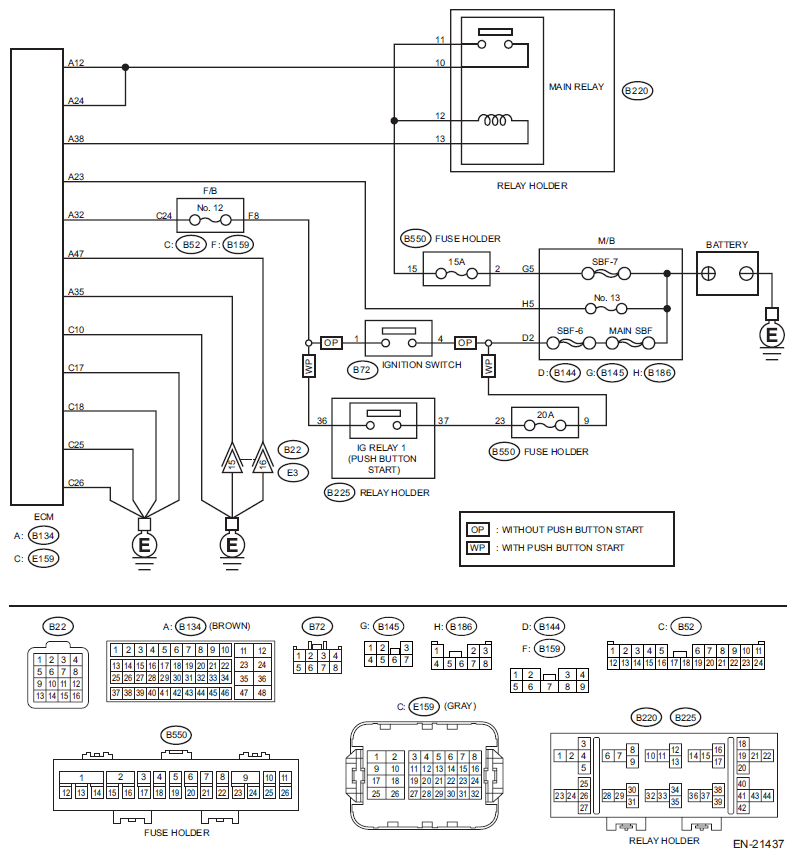 Courtesy of SUBARU OF AMERICA, INC.
| Step |
Check |
Yes |
No |
1 CHECK ECM CONNECTOR.
Check the connecting condition of ECM connector. |
Is the ECM connector correctly connected? |
Go to step 2
. |
Connect the ECM connector correctly. |
2 CHECK INPUT VOLTAGE OF ECM.
- Turn the ignition switch to ON.
- Connect the check board. ST 18460AA030 CHECK BOARD
- Measure the voltage between ECM connector and engine ground while wiggling the harness between ECM connector and ignition switch connector (for models without push button start), or between ECM connector and IG relay 1 (push button start) connector (for models with push button start).
Connector & terminal
(B134) No. 32 (+) - Engine ground (-): |
Is the voltage 8 V or more all the time? |
Even if DTC is detected, the circuit has returned to a normal condition at this time. Reproduce the failure, and then perform the diagnosis again.
NOTE:
In this case, the following items may be the cause of fault. Model without push button start
- Open circuit or short circuit to ground in harness between ECM connector and ignition switch connector
- Poor contact of ignition switch connector
- Poor contact of ignition switch Model with push button start
- Open circuit or short circuit to ground in harness between ECM connector and IG relay 1 (push button start) connector
- Poor contact in IG relay 1 (push button start) connector
- Poor contact in IG relay 1 (push button start)
|
Repair the harness and connector.
NOTE:
In this case, repair the following item: Model without push button start
- Open circuit or short circuit to ground in harness between ECM connector and ignition switch connector
- Poor contact of ignition switch connector
- Poor contact of ignition switch
- Faulty fuse (F/B No. 12) Model with push button start
- Open circuit or short circuit to ground in harness between ECM connector and IG relay 1 (push button start) connector
- Poor contact in IG relay 1 (push button start) connector
- Poor contact in IG relay 1 (push button start)
- Faulty fuse (F/B No. 12)
|