DTC P0032 A/F/O2 Heater Control Circuit High Bank 1 Sensor 1: Notes
DTC DETECTING CONDITION:
Immediately at fault recognition
CAUTION:
- After servicing or replacing faulty parts, perform Clear Memory Mode <Ref. to
OPERATION
, Clear Memory Mode.>, and Inspection Mode <Ref. to
PROCEDURE
, Inspection Mode.>.
- Use the check board when measuring the ECM terminal voltage and resistance.
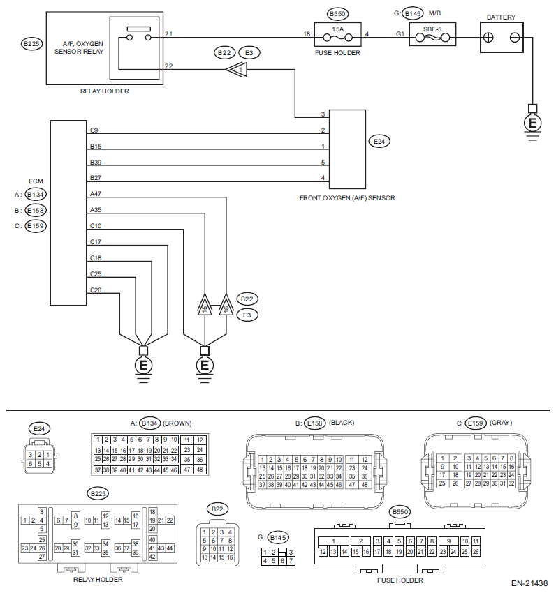
WIRING DIAGRAM:
Engine Electrical System <Ref. to
WIRING DIAGRAM
, Engine Electrical System.>
 Courtesy of SUBARU OF AMERICA, INC.
| Step |
Check |
Yes |
No |
1 CHECK HARNESS BETWEEN ECM AND FRONT OXYGEN (A/F) SENSOR CONNECTOR.
- Turn the ignition switch to OFF.
- Measure the voltage between ECM connector and engine ground.
Connector & terminal
(E159) No. 9 (+) - Engine ground (-):
|
Is the voltage 10 V or more? |
Repair the short circuit to power in the harness between ECM connector and front oxygen (A/F) sensor connector. |
Go to step 2
. |
2 CHECK GROUND CIRCUIT FOR ECM.
- Disconnect the connector from ECM.
- Measure the resistance between the ECM connector and engine ground.
Connector & terminal
(B134) No. 35 - Engine ground:
(B134) No. 47 - Engine ground:
(E159) No. 10 - Engine ground:
(E159) No. 17 - Engine ground:
(E159) No. 18 - Engine ground:
(E159) No. 25 - Engine ground:
(E159) No. 26 - Engine ground:
|
Is the resistance less than 5 Ω? |
Repair the poor contact of ECM connector. |
Repair the harness and connector.
NOTE:
In this case, repair the following item:
- Open circuit of harness between ECM connector and engine ground
- Poor contact of coupling connector
|