- Turn the ignition switch to OFF.
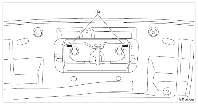
- Open the front hood, and make alignment marks (A) on the front hood striker and the front hood using a marker pen.
 Courtesy of SUBARU OF AMERICA, INC.
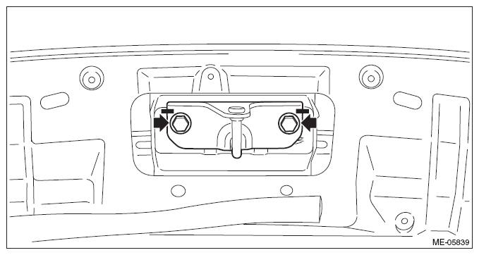
- Remove the front hood striker from the front hood.
 Courtesy of SUBARU OF AMERICA, INC.
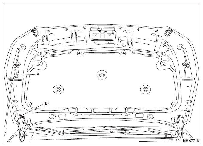
- Change the front hood stay position from (A) to (B), and completely open the front hood.
 Courtesy of SUBARU OF AMERICA, INC.
- Disconnect the ground cable from battery. < Ref. to
BATTERY
, NOTE, Note. >
NOTE:
For the 12 volt engine restart battery, disconnect the ground terminal from 12V engine restart battery sensor.
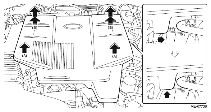
- Remove the collector cover.
- Carefully pull up the front of collector cover at two positions (A).
- Carefully pull up the rear of collector cover at two positions (B) while moving it backward.
NOTE:
Be careful not to contact the fuel delivery tube when moving the collector cover rearward.
 Courtesy of SUBARU OF AMERICA, INC.
- Remove the air intake duct. < Ref. to
REMOVAL
, Air Intake Duct. >
- Remove the air cleaner case. < Ref. to
REMOVAL
, Air Cleaner Case. >
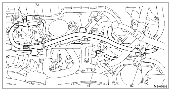
- Disconnect the connector (A) from the brake vacuum pump, and disconnect the connector (B) from the A/C compressor.
- Remove the clip (C) and the clip (D) securing the harness to the battery cable assembly, and move the harness to the left side wheel apron.
 Courtesy of SUBARU OF AMERICA, INC.
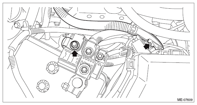
- Remove the terminal boot from the positive terminal of the 12 volt auxiliary battery.
- Remove the nuts fastening the battery cable assembly to the slow blow fuse (12 volt auxiliary battery), and remove the battery cable assembly from the main fuse box.
 Courtesy of SUBARU OF AMERICA, INC.
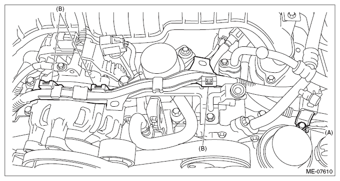
- Remove the bolt (A) securing the battery cable stay to the chain cover, and remove the clip (B) securing the battery cable assembly to the collector cover bracket.
 Courtesy of SUBARU OF AMERICA, INC.
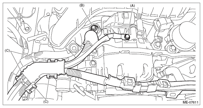
- Disconnect the terminal (A) and the terminal (B) from ISG.
- Remove the clip (C) securing the battery cable assembly to the battery cable bracket No. 1, and move the battery cable assembly to the right side wheel apron.
 Courtesy of SUBARU OF AMERICA, INC.
- Lift up the vehicle.
- Remove the under cover. < Ref. to
REMOVAL
, Front Under Cover. >
- Drain the engine oil. < Ref. to
REPLACEMENT , Engine Oil. >
- Remove the front exhaust pipe. < Ref. to
REMOVAL
, Front Exhaust Pipe. >
- Disconnect the oil level switch connector from the engine harness, and remove the clip (A) securing the harness.
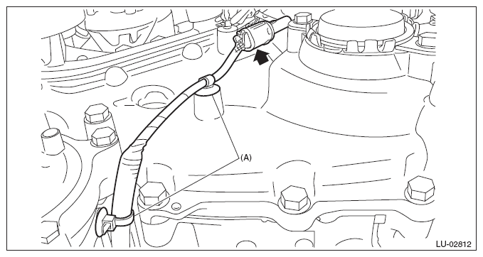 Courtesy of SUBARU OF AMERICA, INC.
- Remove the nuts which secure the engine mounting to the front crossmember.
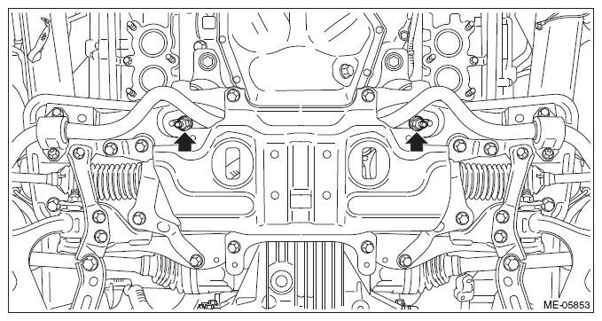 Courtesy of SUBARU OF AMERICA, INC.
- Remove the electric power steering gearbox. < Ref. to
REMOVAL
, Electric Power Steering Gearbox. >
- Remove the front drive shaft LH. < Ref. to
REMOVAL
, Front Drive Shaft. >
- Lower the vehicle.
- Disconnect the transmission radio ground terminal (A) from the vehicle, and remove the pitching stopper.
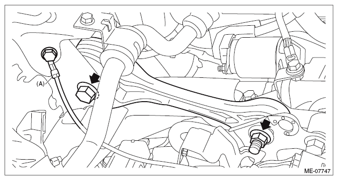 Courtesy of SUBARU OF AMERICA, INC.
- Remove the bolt (A) securing the bulkhead harness connector bracket, and disconnect the bulkhead harness connector from the engine harness connector (brown) (B).
- Disconnect the bulkhead harness connector from the transmission harness connector (C), inhibitor harness connector (D) and drive motor harness connector (E).
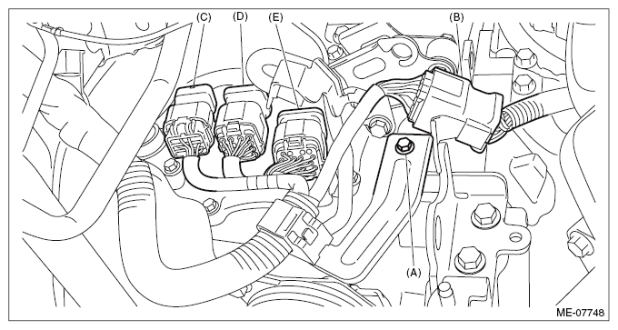 Courtesy of SUBARU OF AMERICA, INC.
- Remove the transmission case cover.
 Courtesy of SUBARU OF AMERICA, INC.
- Remove the bolt which holds the transmission harness stay.
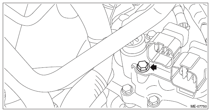 Courtesy of SUBARU OF AMERICA, INC.
- Remove the bolt which holds the transmission harness to the control valve body, and turn the transmission harness clockwise till the bolt hole can be seen as shown in the figure, and tighten the bolt to temporary lock the harness. (CVT model)
NOTE:
This procedure is required to prevent the transmission harness from touching the vehicle body during engine removal/installation.
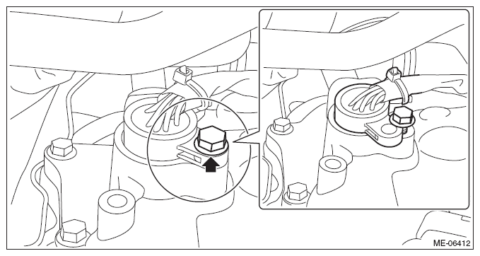 Courtesy of SUBARU OF AMERICA, INC.
- Remove the clip (A) securing the engine harness to the purge control solenoid valve bracket, and disconnect the bolt securing the purge control solenoid valve bracket to the intake manifold.
NOTE:
This operation is required to prevent the wire rope from contacting the purge control solenoid valve while lifting the engine.
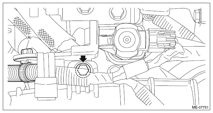 Courtesy of SUBARU OF AMERICA, INC.
- Lift up the engine with a lifting device and wire ropes.
CAUTION:
When lifting up the engine, pay attention to the clearance of each part and be careful not to lift the engine too much, in order to prevent damaging the vehicle.
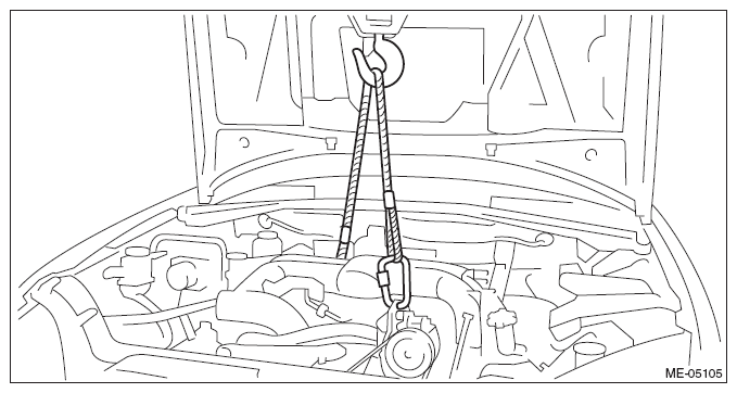 Courtesy of SUBARU OF AMERICA, INC.
- Remove the engine mounting LH from the engine.
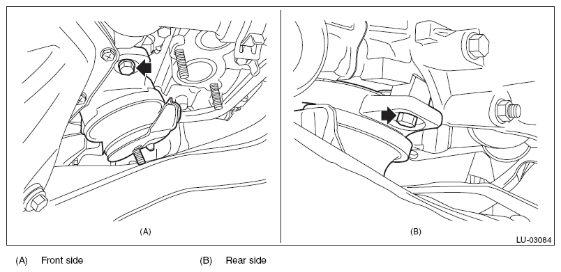 Courtesy of SUBARU OF AMERICA, INC.
- Remove clip (A) from the oil pan upper, and remove the oil level switch.
 Courtesy of SUBARU OF AMERICA, INC.