Intake Manifold: Disassembly
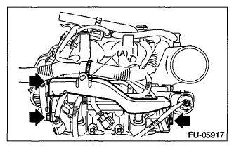
- Remove clamp (A) holding the fuel pipe protector RH to the engine harness, and remove the fuel pipe protector RH.
 Courtesy of SUBARU OF AMERICA, INC.
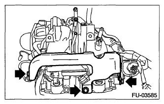
- Remove the fuel pipe protector LH.
 Courtesy of SUBARU OF AMERICA, INC.
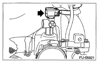
- Remove the connector from the intake duct.
 Courtesy of SUBARU OF AMERICA, INC.
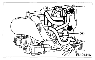
- Remove purge control solenoid valve 1 (A) and purge control solenoid valve 2 (B).
 Courtesy of SUBARU OF AMERICA, INC.
- Remove the solenoid valve bracket together with the wastegate control solenoid valve.
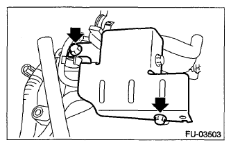 Courtesy of SUBARU OF AMERICA, INC.
- Remove the engine ground terminals from the intake manifold.
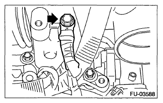 Courtesy of SUBARU OF AMERICA, INC.
- Disconnect the connector (A) from the throttle position sensor, and the connector (B) from the manifold pressure sensor.
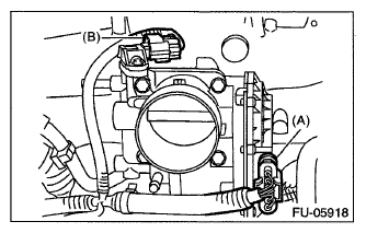 Courtesy of SUBARU OF AMERICA, INC.
- Remove clip (A) holding the engine harness and vacuum hose, clip (B) holding the engine harness to the engine harness stay, and the bolt holding the engine harness to the intake manifold.
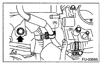 Courtesy of SUBARU OF AMERICA, INC.
- Remove the throttle body from the intake manifold.
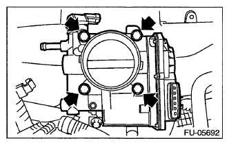 Courtesy of SUBARU OF AMERICA, INC.
- Remove the harness band (A) which holds the engine harness to the fuel injector pipe.
- RH side
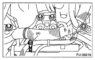 Courtesy of SUBARU OF AMERICA, INC.
- LH side
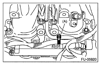 Courtesy of SUBARU OF AMERICA, INC.
- Disconnect the connector from fuel injector.
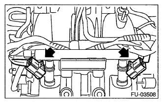 Courtesy of SUBARU OF AMERICA, INC.
- Disconnect the connector from the tumble generator valve assembly.
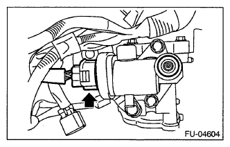 Courtesy of SUBARU OF AMERICA, INC.
- Remove the bolts which hold fuel injector pipe.
- RH side
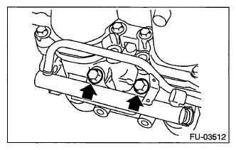 Courtesy of SUBARU OF AMERICA, INC.
- LH side
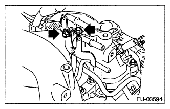 Courtesy of SUBARU OF AMERICA, INC.
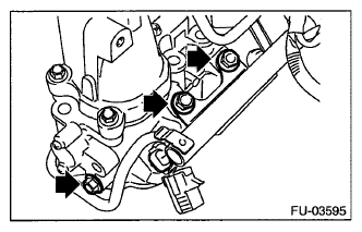 Courtesy of SUBARU OF AMERICA, INC.
- Remove the fuel injector.
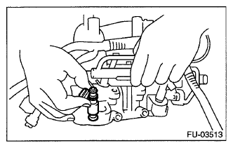 Courtesy of SUBARU OF AMERICA, INC.
- Remove the harness brackets holding the engine harness to the intake manifold, and remove the engine harness.
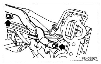 Courtesy of SUBARU OF AMERICA, INC.
- Loosen the clamp holding the RH side fuel hose to the fuel injector pipe RH, and remove the fuel injector pipe RH.
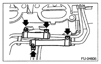 Courtesy of SUBARU OF AMERICA, INC.
- Loosen the clamp holding the LH side fuel hose to the fuel injector pipe LH, and remove the fuel injector pipe LH.
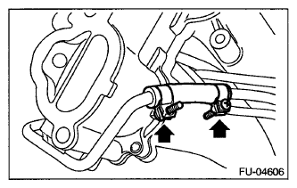 Courtesy of SUBARU OF AMERICA, INC.
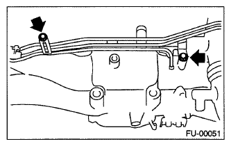
- Remove the bolts holding the fuel pipe assembly to the intake manifold, and remove the fuel pipe assembly.
 Courtesy of SUBARU OF AMERICA, INC.
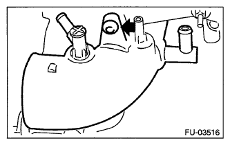
- Remove the intake duct from intake manifold.
 Courtesy of SUBARU OF AMERICA, INC.
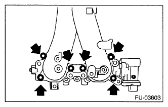
- Remove the tumble generator valve assembly from the intake manifold.
 Courtesy of SUBARU OF AMERICA, INC.
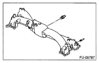
- Remove the nipple from the intake manifold.
 Courtesy of SUBARU OF AMERICA, INC.