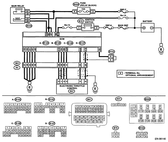
DTC P0607 Throttle Control System Circuit Range/Performance: Wiring Diagram
 Courtesy of SUBARU OF AMERICA, INC.
 DIAGNOSIS PROCEDURE CHART
| Step |
Check |
Yes |
No |
1 CHECK INPUT VOLTAGE OF ECM
.
- Turn the ignition switch to ON.
- Measure the voltage between ECM and chassis ground.
Connector & terminal
(B134) No. 7 (+) - Chassis ground (-):
(B135) No. 2 (+) - Chassis ground (-):
|
Is the voltage 10 - 13 V? |
Go to step 2
. |
Repair the open or ground short circuit of power supply circuit. |
2 CHECK INPUT VOLTAGE OF ECM
.
- Start the engine.
- Measure the voltage between ECM and chassis ground.
Connector & terminal
(B134) No. 7 (+) - Chassis ground (-):
(B135) No. 2 (+) - Chassis ground (-):
|
Is the voltage 13 - 15 V? |
Go to step 3
. |
Repair the open or ground short circuit of power supply circuit. |
3 CHECK HARNESS BETWEEN ECM AND ELECTRONIC THROTTLE CONTROL
.
- Turn the ignition switch to OFF.
- Disconnect the connectors from ECM and electronic throttle control.
- Measure the resistance of harness between ECM and electronic throttle control connector.
Connector & terminal
(B134) No. 19 - (E57) No. 5:
(B134) No. 29 - (E57) No. 3:
|
Is the resistance less than 1 Ω? |
Go to step 4
. |
Repair the open circuit of harness between ECM and electronic throttle control connector. |
4 CHECK ECM GROUND HARNESS
.
- Connect all connectors.
- Turn the ignition switch to ON.
- Measure the voltage between ECM and chassis ground.
Connector & terminal
(B134) No. 5 (+) - Chassis ground (-)
(B137) No. 1 (+) - Chassis ground (-)
(B137) No. 2 (+) - Chassis ground (-)
(B137) No. 3 (+) - Chassis ground (-)
(B137) No. 7 (+) - Chassis ground (-)
|
Is the voltage less than 1 V? |
Repair the poor contact of the ECM connector. |
Repair the following item.
- Open circuit in ground circuit
- Further tightening of the engine ground terminal
- Poor contact in ECM connector
- Poor contact of coupling connector
|