Starting/Charging Systems (H6DO): Starter: Disassembly
- Loosen the nut which holds terminal M of magnet switch assembly, and then disconnect the harness from terminal.
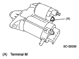 Courtesy of SUBARU OF AMERICA, INC.
- Remove the bolts which hold switch assembly, and then remove the switch assembly, plunger and plunger spring from starter.
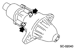 Courtesy of SUBARU OF AMERICA, INC.
- Remove the nuts of both sides, and then remove the rear cover.
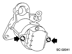 Courtesy of SUBARU OF AMERICA, INC.
- Remove the through-bolts of bolt side, and then detach the end frame and armature from yoke as a unit.
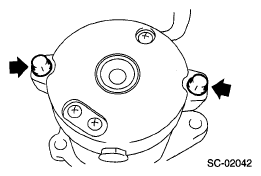 Courtesy of SUBARU OF AMERICA, INC.
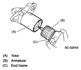 Courtesy of SUBARU OF AMERICA, INC.
- Remove the end frame cover.
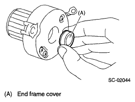 Courtesy of SUBARU OF AMERICA, INC.
- Remove the snap ring.
- Remove the space ring.
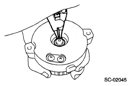 Courtesy of SUBARU OF AMERICA, INC.
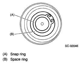 Courtesy of SUBARU OF AMERICA, INC.
- Remove the armature from end frame.
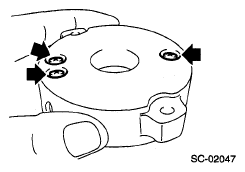
- Remove the screws.
 Courtesy of SUBARU OF AMERICA, INC.
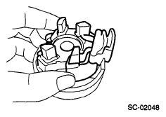
- Remove the brush holder assembly from end frame.
 Courtesy of SUBARU OF AMERICA, INC.
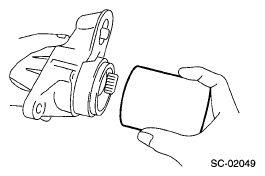
- Remove the yoke from front bracket.
 Courtesy of SUBARU OF AMERICA, INC.
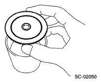
- Remove the armature plate from the yoke.
 Courtesy of SUBARU OF AMERICA, INC.
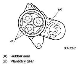
- Remove the rubber seal and planetary gear.
 Courtesy of SUBARU OF AMERICA, INC.
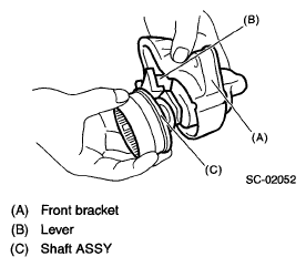
- Remove the shaft assembly, overrunning clutch and lever from front bracket as a unit.
 Courtesy of SUBARU OF AMERICA, INC.
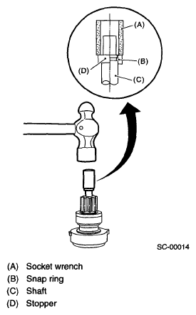
- Remove the overrunning clutch from shaft assembly as follows:
- Remove the stopper from snap ring by lightly tapping the stopper with an appropriate tool (such as a fit socket wrench).
- Remove the snap ring, stopper and clutch from shaft.
 Courtesy of SUBARU OF AMERICA, INC.
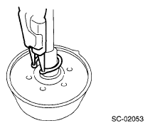
- Remove the snap ring.
 Courtesy of SUBARU OF AMERICA, INC.
- Remove the shock absorber bearing, wave washer and internal gear from shaft.
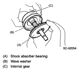 Courtesy of SUBARU OF AMERICA, INC.
- Remove the front bearing from front bracket.
- Set an appropriate tool (diameter 13 mm) to front bearing.
- Using a press, remove the front bearing.
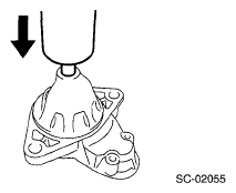 Courtesy of SUBARU OF AMERICA, INC.
- Remove the oilless bearing from shock absorber bearing.
- Set an appropriate tool (diameter 20 mm) to oilless bearing.
- Using a press, remove the oilless bearing.
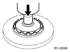 Courtesy of SUBARU OF AMERICA, INC.
- Remove the rear bearing from end frame.
- Set an appropriate tool (diameter 16 mm) to rear bearing.
- Using a press, remove the rear bearing.
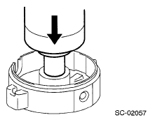 Courtesy of SUBARU OF AMERICA, INC.