DTC P1596: A/T Diagnosis Input Signal Circuit High Input (Forester, IMPREZA & Outback Sport)
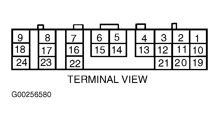
- Perform test procedure. See TESTING PROCEDURE . Turn ignition on. Using a DVOM, measure voltage of Brown/Red wire by backprobing between 28-pin ECM electrical harness connector B135 terminal No. 4 and good chassis ground point. See Figure. If voltage is not more than 10 volts, go to next step. If voltage is more than 10 volts, repair short to voltage in wiring between ECM and transmission control module. After repair, replace ECM. Clear memory and perform verification procedure. See CLEARING DIAGNOSTIC TROUBLE CODES and VERIFICATION PROCEDURE
.
- Using a DVOM, measure voltage of Brown/Red wire by backprobing between 28-pin ECM electrical harness connector B135 terminal No. 4 and good chassis ground point. See Figure. If voltage is not more than 4 volts, go to next step. If voltage is more than 4 volts, go to step 5.
- Using a DVOM, measure voltage of Brown/Red wire by backprobing between 28-pin ECM electrical harness connector B135 terminal No. 4 and good chassis ground point. See Figure. If voltage is not less than one volt, go to next step. If voltage is less than one volt, repair poor terminal contact in 28-pin ECM connector B135. Clear memory and perform verification procedure. See CLEARING DIAGNOSTIC TROUBLE CODES and VERIFICATION PROCEDURE
.
- Using a DVOM, measure voltage of Brown/Red wire by backprobing between 28-pin ECM electrical harness connector B135 terminal No. 4 and good chassis ground point. See Figure. If voltage toggles between one and 4 volts, circuit has returned to normal. Check for intermittent conditions. See INTERMITTENTS
in TROUBLE SHOOTING - NO CODES article. If voltage does not toggle between one and 4 volts, contact authorized Subaru dealership because probable cause is deterioration of multiple parts. Clear memory and perform verification procedure. See CLEARING DIAGNOSTIC TROUBLE CODES and VERIFICATION PROCEDURE
.
- Using a DVOM, measure voltage of Brown/Red wire by backprobing between 24-pin transmission control module (TCM) electrical harness connector B54 terminal No. 4 and good chassis ground point. See Fig 1. If voltage is more than 4 volts, go to next step. If voltage is not more than 4 volts, repair open circuit in wiring between ECM and TCM. See ENGINE PERFORMANCE in appropriate SYSTEM WIRING DIAGRAMS article in ELECTRICAL. Clear memory and perform verification procedure. See CLEARING DIAGNOSTIC TROUBLE CODES and VERIFICATION PROCEDURE
.
- Check for poor terminal contact in 24-pin TCM electrical harness connector B54. Repair as necessary. If terminal contact is okay, check TCM power and ground circuits. See appropriate DIAGNOSTICS article in AUTOMATIC TRANSMISSIONS in TRANSAXLE/TRANSMISSION. Clear memory and perform verification procedure. See CLEARING DIAGNOSTIC TROUBLE CODES and VERIFICATION PROCEDURE
.
 Courtesy of SUBARU OF AMERICA, INC.