Actuator Valve
- Measure resistance of actuator. SeeFig 1
. See ACTUATOR VALVE RESISTANCES
. If resistance is as specified, go to next step.
- Connect positive battery power to actuator terminal No. 2 and ground actuator terminals No. 1, 3 or 4. Using a vacuum pump, ensure control cable moves smoothly when 11.81 In. Hg is applied to actuator. Stroke should equal 1.38" (35 mm) within 3 seconds.
- When ground is disconnected, control cable should return to its original position smoothly. Return movement should occur within 1.5 seconds. Test remaining terminals in similar fashion. If actuator works as specified, go to next step.
ACTUATOR VALVE RESISTANCES
| Terminals |
Ohms Resistance |
| Terminal No. 1 To No. 2 (Vent Valve) |
55 |
| Terminal No. 2 To No. 3 (Vacuum Valve) |
22 |
| Terminal No. 2 To No. 4 (Safety Valve) |
55 |
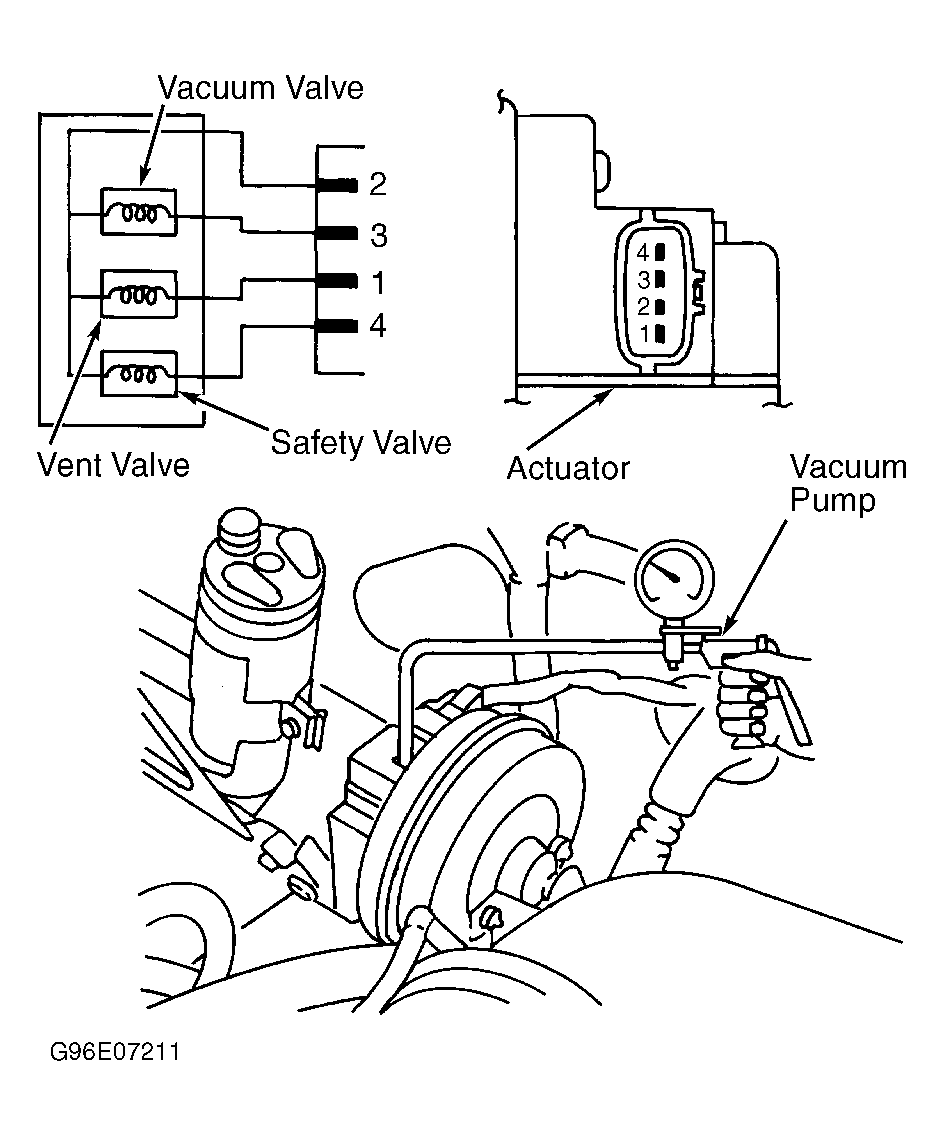 Courtesy of SUBARU OF AMERICA, INC.
- Perform a circuit test in harness between cruise control module and actuator. Separate both sides of connectors. Perform a circuit test between each of the harnesses. See ACTUATOR HARNESS RESISTANCE
. SeeFig 2
.
ACTUATOR HARNESS RESISTANCE
| Connector & Terminal |
Ohms Resistance |
| (B7) No. 1 To (B54) No. 1 |
10 |
| (B7) No. 2 To (B54) No. 8 |
10 |
| (B7) No. 3 To (B54) No. 11 |
10 |
| (B7) No. 4 To (B54) No. 2 |
10 |
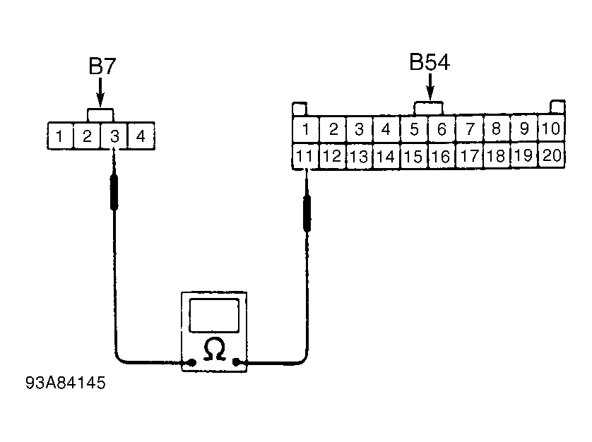 Courtesy of SUBARU OF AMERICA, INC.