Removal Procedure
 Courtesy of GENERAL MOTORS CORP.
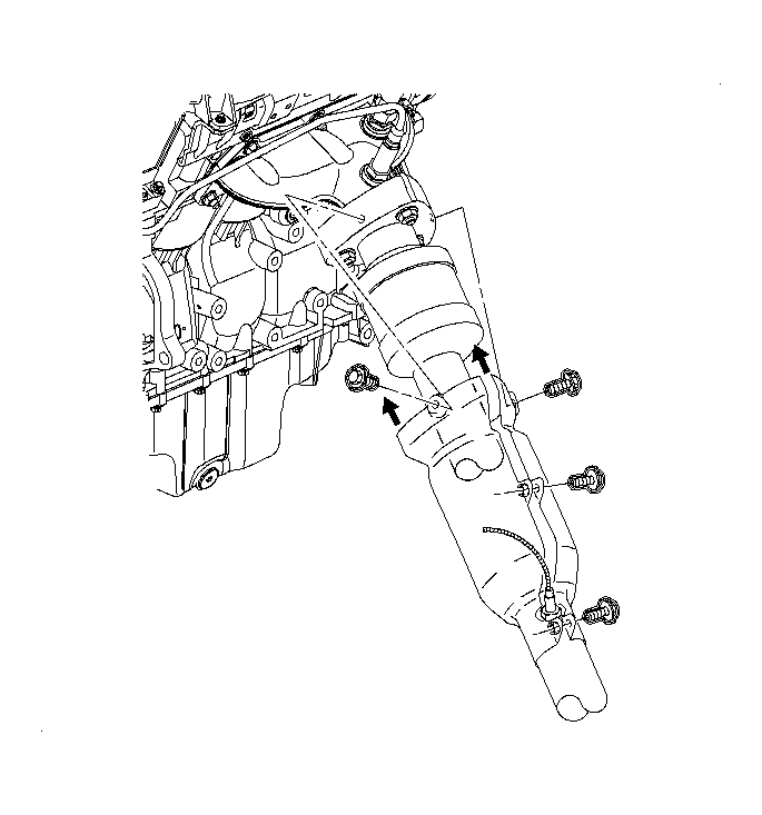
- If equipped with a L81 engine, remove the rear exhaust manifold pipe heat shield. Refer to Exhaust Pipe Heat Shield Replacement
in Engine Exhaust.
 Courtesy of GENERAL MOTORS CORP.
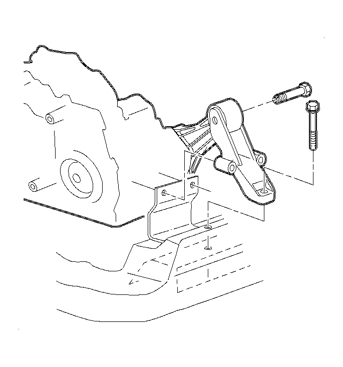
- Remove the rear transaxle mount through bolt and transaxle mount to frame bolt.
 Courtesy of GENERAL MOTORS CORP.
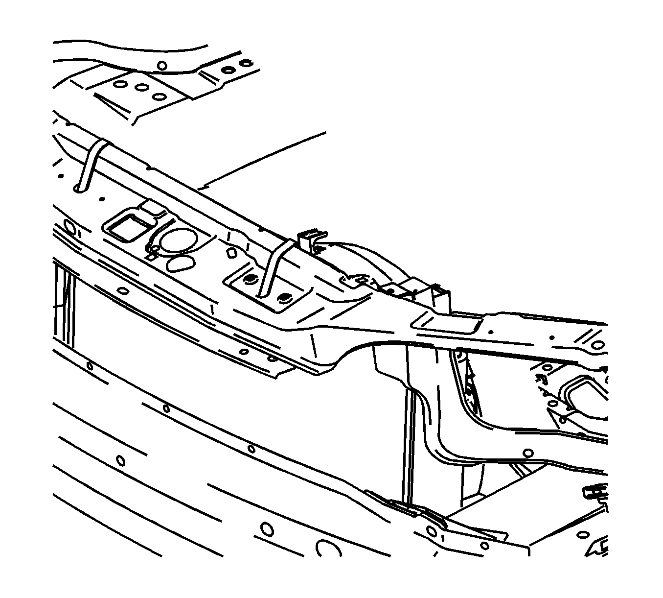
- Secure the radiator to the upper radiator support.
- Raise and support the vehicle. Refer to Lifting and Jacking the Vehicle
in General Information.
- Remove the front tires and wheels. Refer to Tire and Wheel Removal and Installation
in Tires and Wheels.
 Courtesy of GENERAL MOTORS CORP.
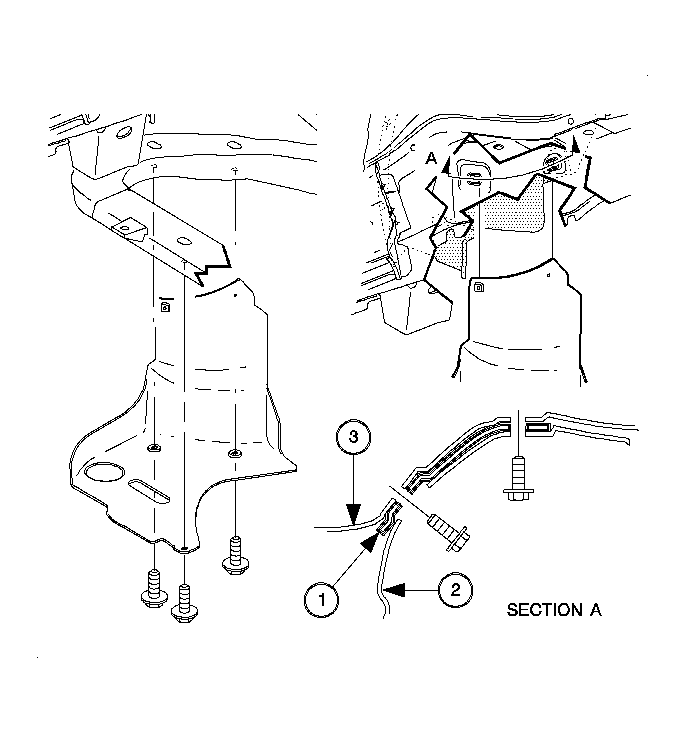
- Remove the right front lower splash shield (2).
- Remove the left front wheel liner push pin from the frame.
 Courtesy of GENERAL MOTORS CORP.
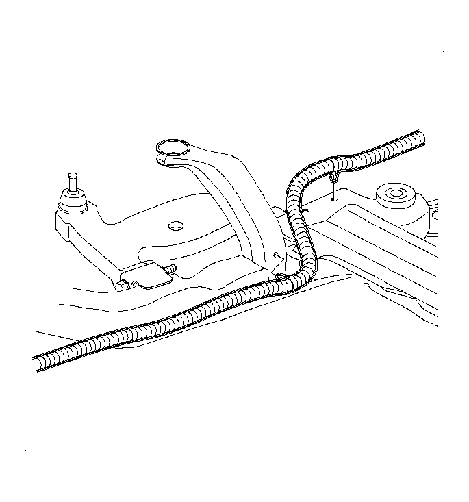
- Disconnect the rear oxygen (O2) sensor harness push pins from the frame.
 Courtesy of GENERAL MOTORS CORP.
- If equipped with a L61 engine, remove the O2 sensor harness to underbody clamp attachment nut.
- Disconnect the exhaust manifold pipe from the exhaust manifold on L61 engine or manifolds on the L81 engine. Refer to Exhaust Manifold Pipe Replacement
in Engine Exhaust.
 Courtesy of GENERAL MOTORS CORP.
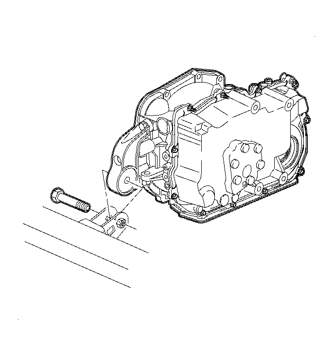
- Remove the front transaxle mount through bolt.
 Courtesy of GENERAL MOTORS CORP.
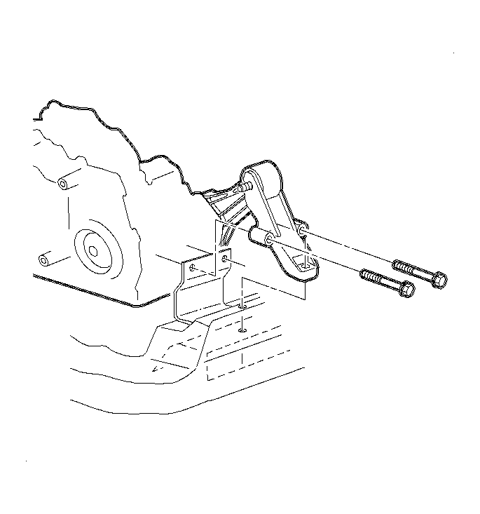
- Remove the remaining rear transaxle mount to frame bolts.
- Remove the rear transaxle mount from the vehicle.
 Courtesy of GENERAL MOTORS CORP.
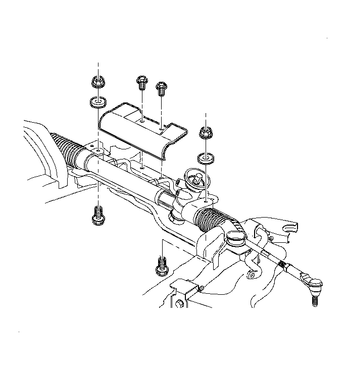
- Remove the steering gear to frame bolts and nuts. Discard the bolts and nuts.
- If equipped with a L61 engine, remove the steering gear heat shield. Refer to Power Steering Gear Heat Shield Replacement
in Power Steering System.
- Using mechanics wire, secure the steering gear to the vehicle body.
 Courtesy of GENERAL MOTORS CORP.
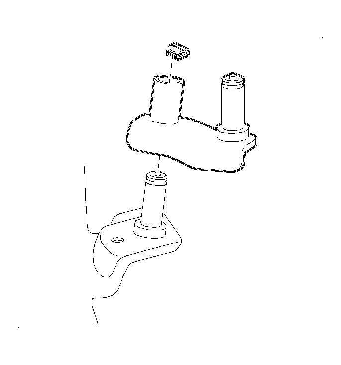
- If equipped with a manual transmission, disconnect the frame to shiftier link pivot pin clip.
 Courtesy of GENERAL MOTORS CORP.
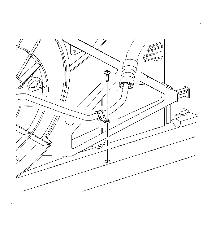
- Disconnect the A/C pipe to frame clip at the front of the vehicle.
 Courtesy of GENERAL MOTORS CORP.
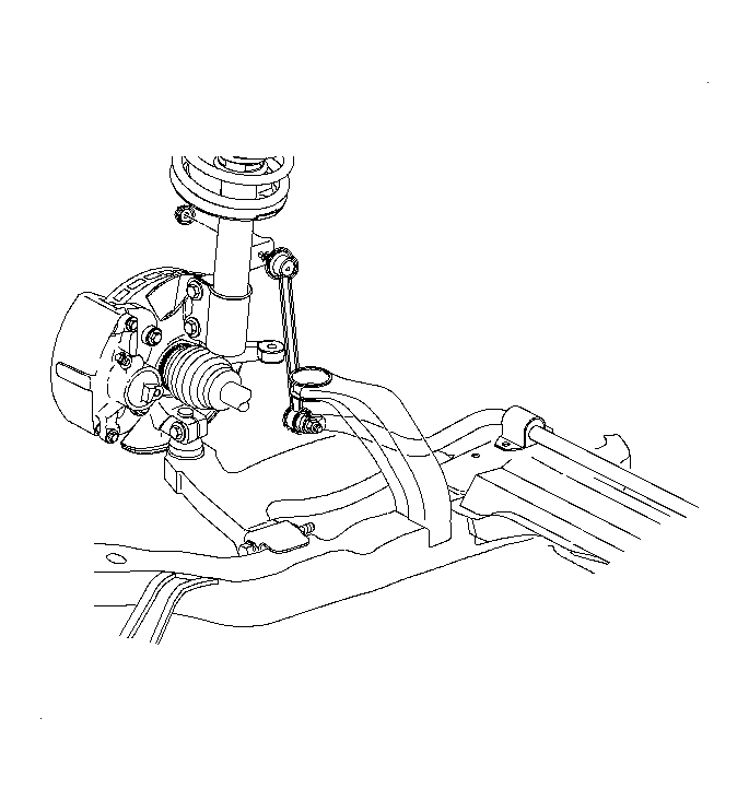
- Disconnect the stabilizer bar link from the struts. Discard the nuts.
 Courtesy of GENERAL MOTORS CORP.
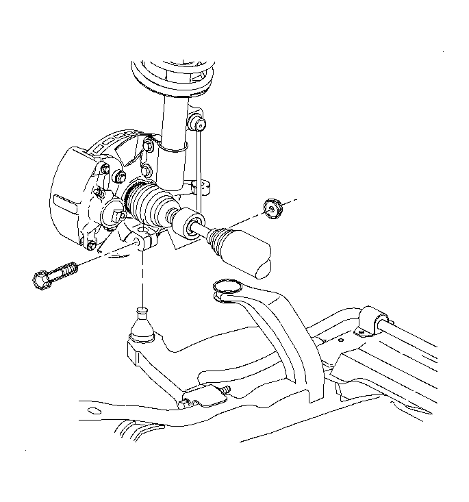
- Disconnect the lower control arms from the steering knuckle. Refer to Lower Control Arm Replacement
in Front Suspension.
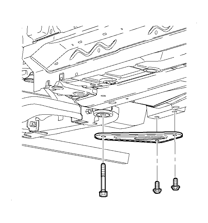 Courtesy of GENERAL MOTORS CORP.
- Remove the suspension support assemblies. Discard the bolts.
- Remove the suspension support cage nuts from the body. Discard the nuts.
- Use a powertrain lifting table and the J 43628
to support the frame assembly. See Special Tools .
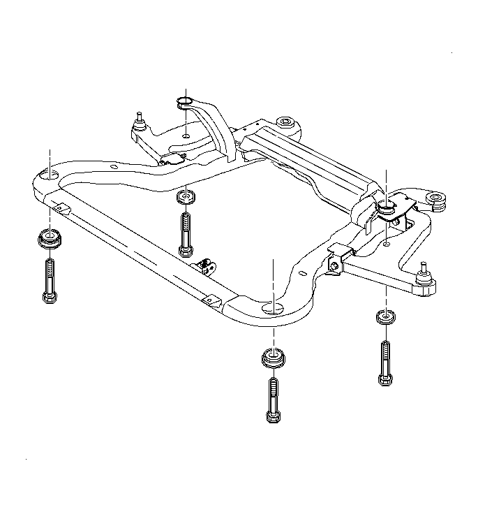 Courtesy of GENERAL MOTORS CORP.
- Remove the remaining frame to body bolts. Discard the frame to body bolts.
- Lower the frame from the vehicle.
- Remove all frame assembly cage nuts from the body and discard.
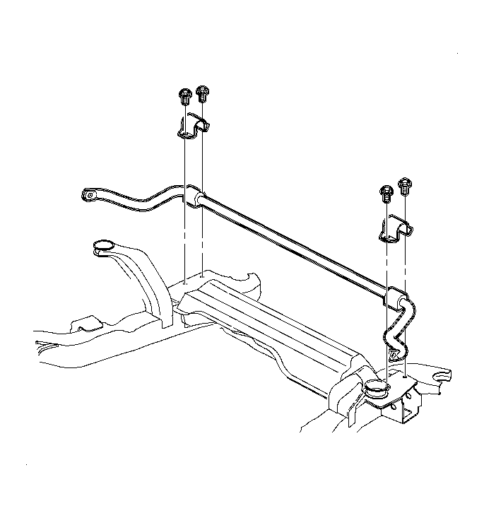 Courtesy of GENERAL MOTORS CORP.
- Remove the stabilizer shaft assembly. Refer to Stabilizer Shaft Replacement (W/L61)
or Stabilizer Shaft Replacement (W/L81)
in Front Suspension.
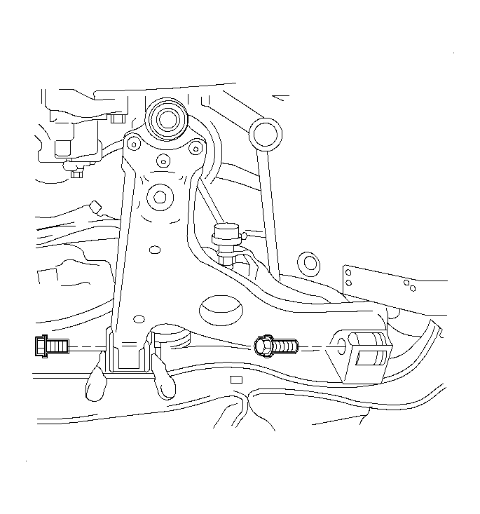 Courtesy of GENERAL MOTORS CORP.
- Remove the lower control arms. Refer to Lower Control Arm Replacement
in Front Suspension.
- Remove the frame assembly from the powertrain lifting table and the J 43628
. See Special Tools .