Removal Procedure
- Disconnect the negative battery cable. Refer to Battery Negative Cable Disconnect/Connect Procedure
in Engine Electrical.
- Remove the cover from the underhood electrical center.
- Release the forward lamp harness retainer from the ABS modulator bracket, or the proportioning valve bracket, to allow the underhood electrical center to be repositioned adequately.
 Courtesy of GENERAL MOTORS CORP.
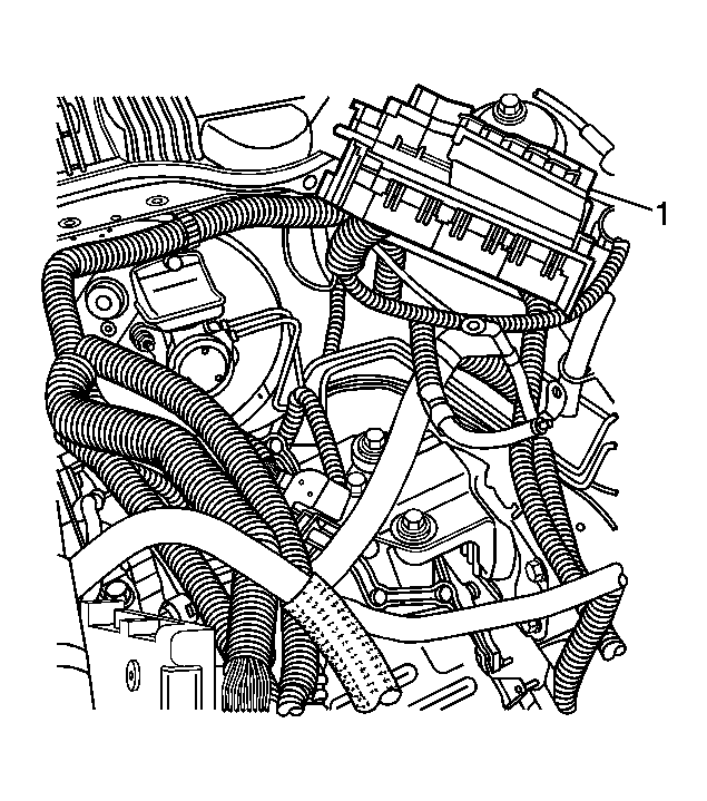
- Remove the underhood electrical center bracket from the vehicle and reposition the electrical center (1) to access the bracket. Refer to Underhood Electrical Center or Junction Block Bracket Replacement
in Wiring Systems.
 Courtesy of GENERAL MOTORS CORP.
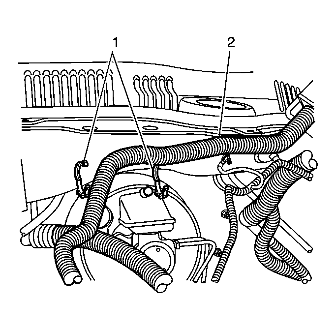
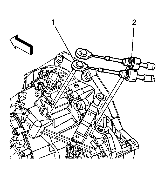
- Release the wiring harness (2) retainers (1) above the brake booster, to allow the electrical center to be repositioned adequately.
 Courtesy of GENERAL MOTORS CORP.
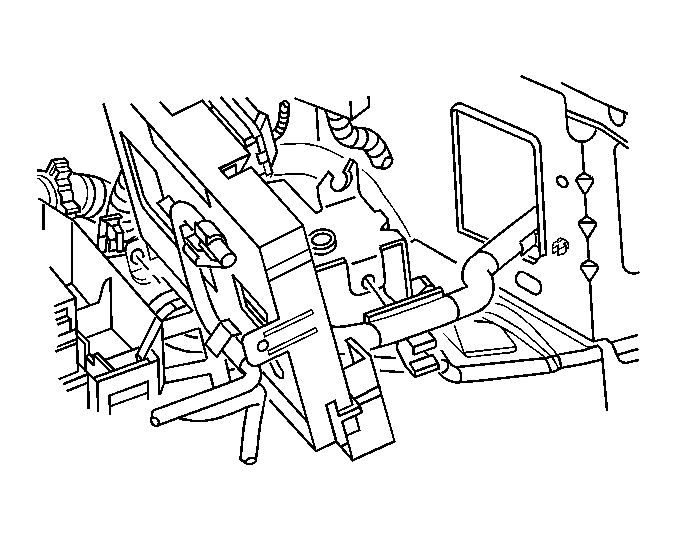
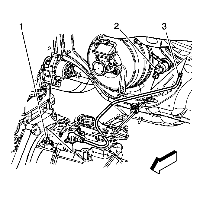
- Disconnect the hydraulic clutch hose (3) from the clutch actuator cylinder (2) and the clutch master cylinder (1).
 Courtesy of GENERAL MOTORS CORP.
- Install the engine support fixture. Refer to Engine Support Fixture
in Engine Mechanical - 2.0L (LSJ).
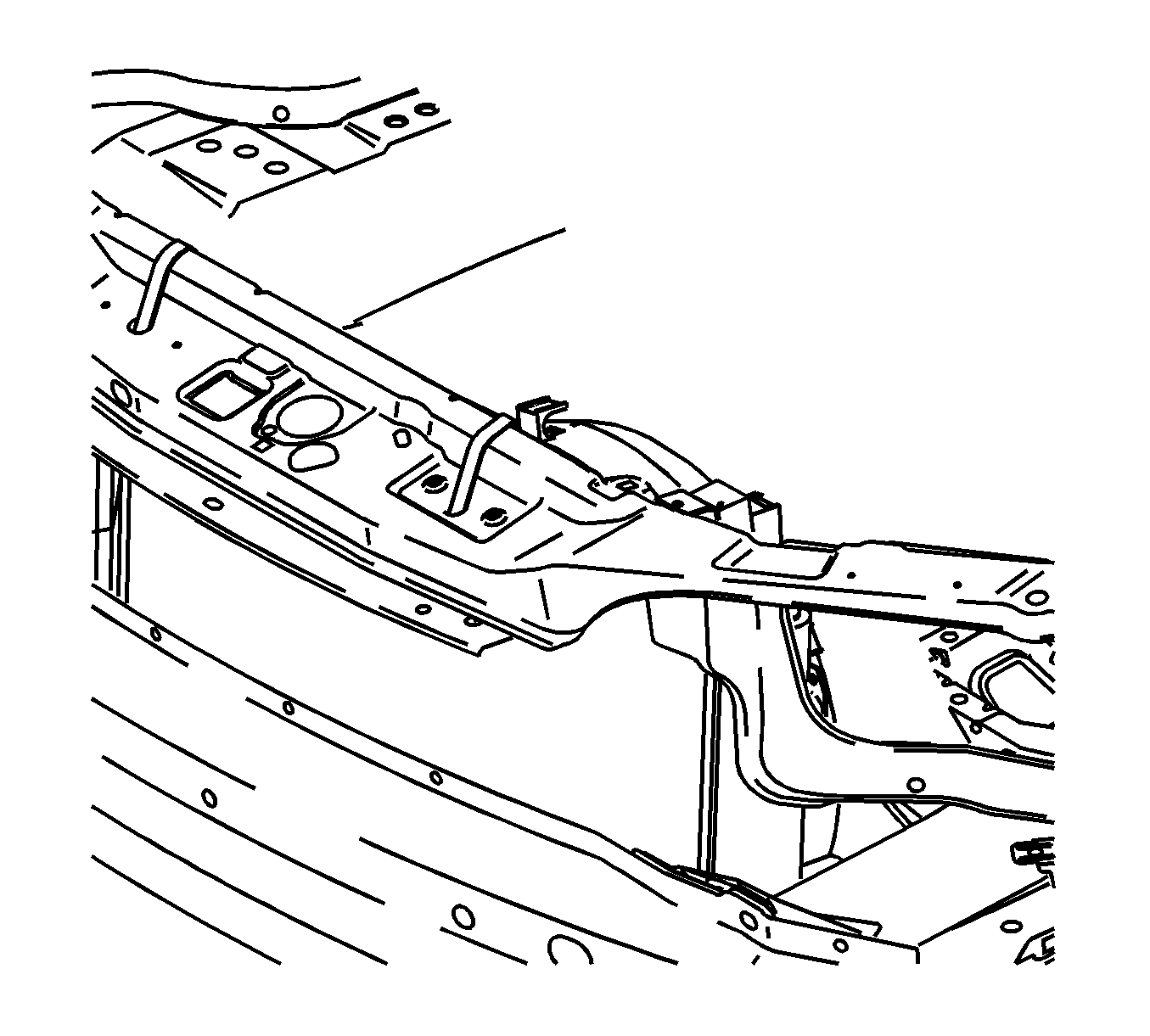
- Secure the cooling module to the upper body structure.
 Courtesy of GENERAL MOTORS CORP.
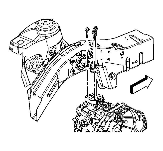
- Remove the upper transmission to mount bolts.
 Courtesy of GENERAL MOTORS CORP.
- Disconnect the wiring harness retainer from the transmission stud.
- Remove the upper transmission to engine stud and bolt.
- Remove the frame. Refer to Frame Replacement
in Frame and Underbody.
- Drain the transaxle. Refer to Transmission Fluid Replacement .
- Disconnect the drive axle and intermediate shaft from the transmission and secure out of the way. Refer to Wheel Drive Shaft Replacement
and Intermediate Drive Shaft Replacement
in Wheel Drive Shafts.
- Remove the starter. Refer to Starter Motor Replacement (2.2L (L61))
or Starter Motor Replacement (2.0L (LSJ))
in Engine Electrical.
- Disconnect the shift cables (2) from the transmission. Refer to Shift Control Cable Replacement .
 Courtesy of GENERAL MOTORS CORP.
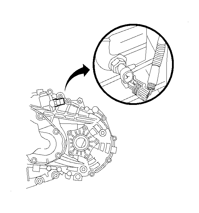
- Disconnect the backup lamp switch harness connector.
 Courtesy of GENERAL MOTORS CORP.
- Lower the vehicle.
- Use the engine support fixture rear hook to lower the powertrain enough to allow clearance between the side rail and powertrain.
- Raise the vehicle. Refer to Lifting and Jacking the Vehicle
in General Information.
- Use a transmission jack to secure the transmission, and remove the transmission to engine bolts.
- Remove the transmission from the vehicle.
- Remove the front transmission mount from the transmission. Refer to Transmission Mount Replacement - Front .
- Remove the rear transmission mount and bracket from the transmission. Refer to Transmission Mount Replacement - Rear .