Removal Procedure
- Place the steering wheel in the straight forward position.
- Remove the steering Wheel. Refer to Steering Wheel Replacement .
- Remove the I/P lower compartment. Refer to Compartment Replacement - Instrument Panel (I/P) - Lower
in Instrument Panel, Gages and Console.
- Remove the column trim covers. Refer to Steering Column Trim Covers Replacement .
 Courtesy of GENERAL MOTORS CORP.
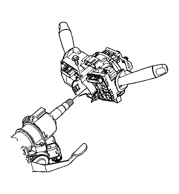
- Disconnect the head lamp/turn signal harness connector from the SIR coil module assembly.
- Disconnect the wiper/washer harness connector from the SIR coil module assembly.
- Disconnect the SIR coil harness connector from the SIR coil module assembly.
 Courtesy of GENERAL MOTORS CORP.
- Remove the SIR coil Module assembly. Refer to Inflatable Restraint Steering Wheel Module Coil Replacement
in SIR.
 Courtesy of GENERAL MOTORS CORP.
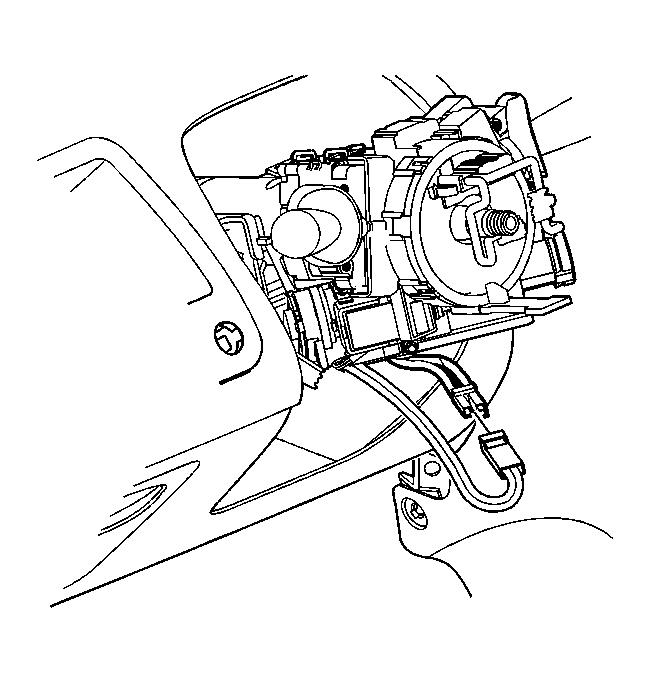
- Disconnect the ignition lock cylinder harness connector.
- Disconnect the ignition switch harness connector.
 Courtesy of GENERAL MOTORS CORP.
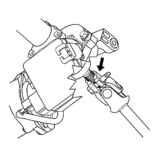
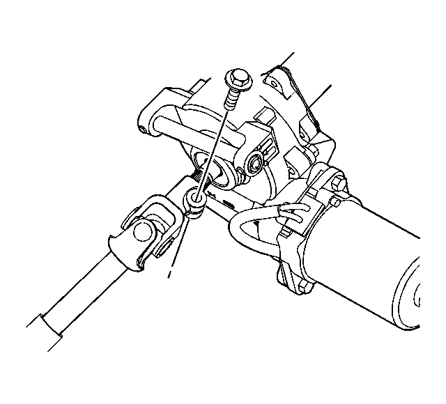
- Place scribe marks on the intermediate shaft to steering column, for use during assembly.
 Courtesy of GENERAL MOTORS CORP.
- Remove the intermediate shaft pinch bolt at the steering column and discard.
 Courtesy of GENERAL MOTORS CORP.
- Slide the intermediate shaft off the steering column.
- Disconnect the EPS control module power feed harness connector.
- Disconnect the EPS control module small harness connector.
 Courtesy of GENERAL MOTORS CORP.
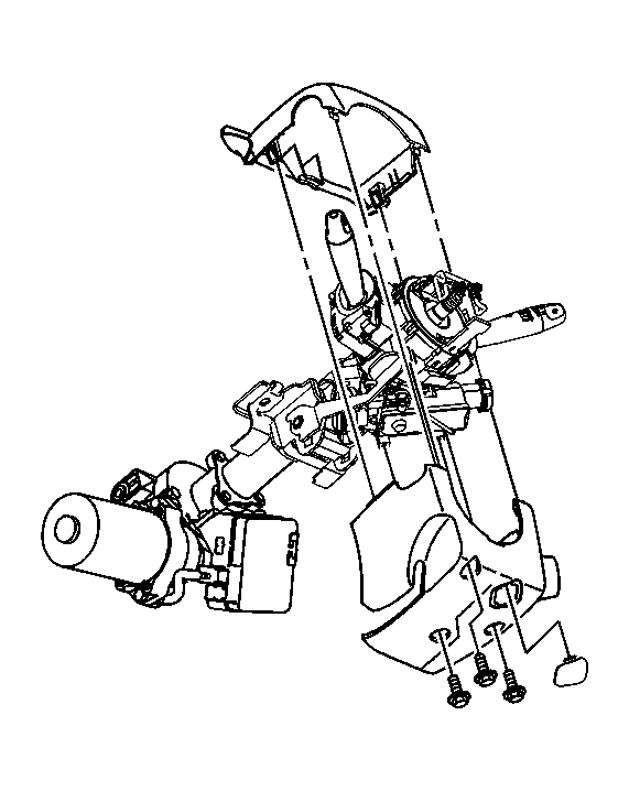
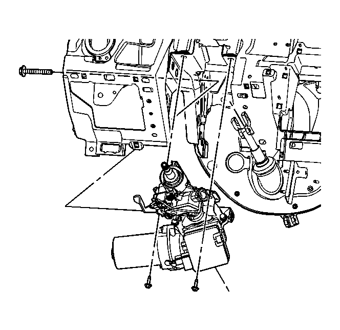
- Remove the steering column pivot Bolt.
- Remove the steering column mounting bolts.
- Remove the column from the vehicle and place on a bench.
 Courtesy of GENERAL MOTORS CORP.
- Remove the ignition lock cylinder case from the steering column. Refer to Ignition Lock Cylinder Case Replacement .
 Courtesy of GENERAL MOTORS CORP.