- On vehicles equipped with L81 engines, remove rear exhaust manifold pipe heat shield.
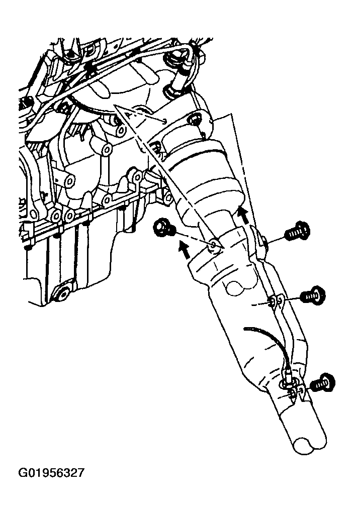 Courtesy of GENERAL MOTORS CORP.
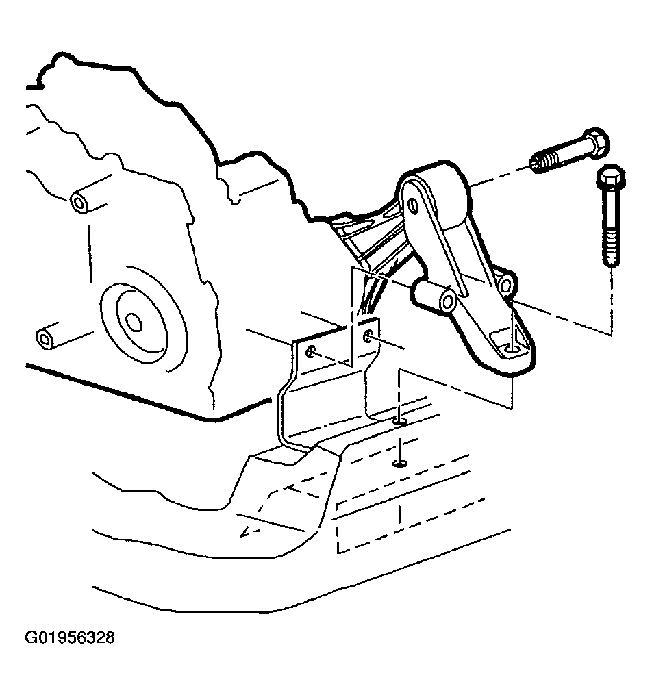
- Remove rear transaxle mount through bolt, and transaxle mount-to-frame bolt.
 Courtesy of GENERAL MOTORS CORP.
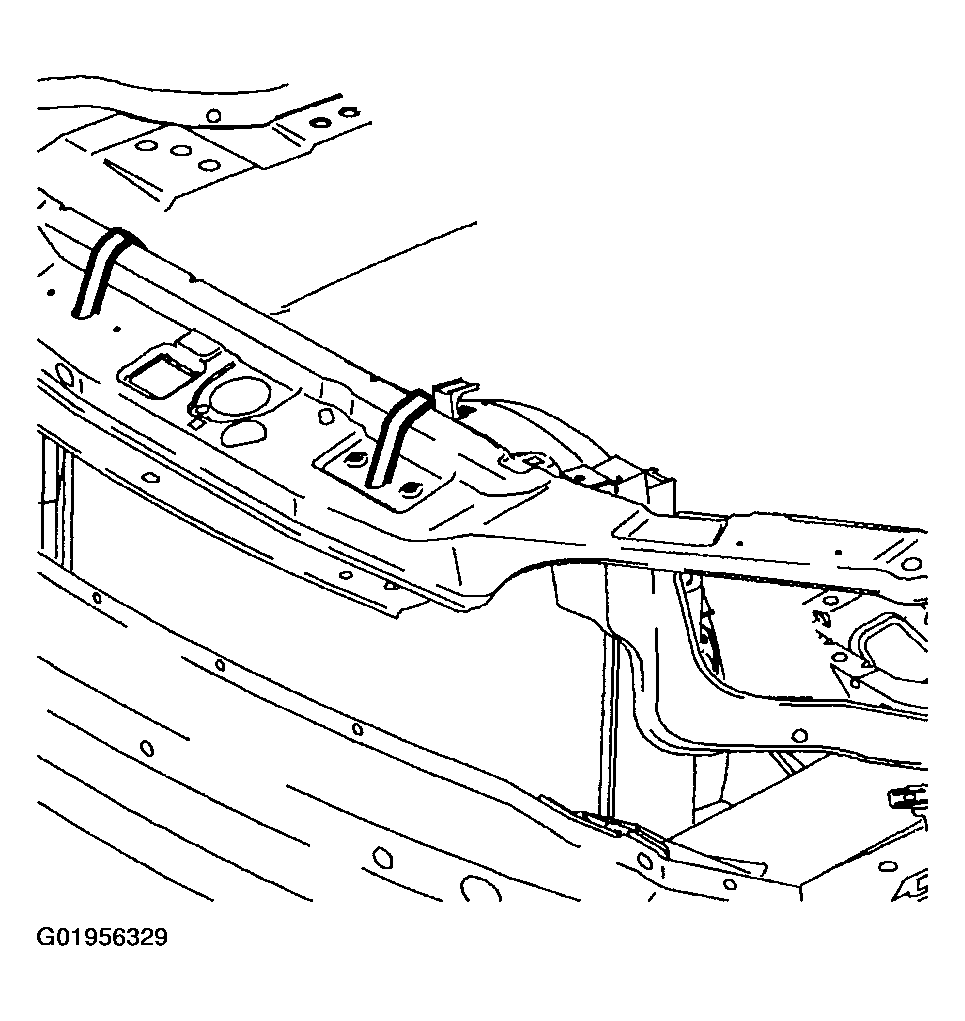
- Fasten radiator to upper radiator support.
WARNING:
Make sure vehicle is properly supported and squarely positioned on the hoist. To help avoid personal injury when a vehicle is on a hoist, provide additional support for the vehicle on the opposite end from which components are being removed.
- Raise vehicle on hoist.
- Remove front wheel and tire assemblies.
 Courtesy of GENERAL MOTORS CORP.
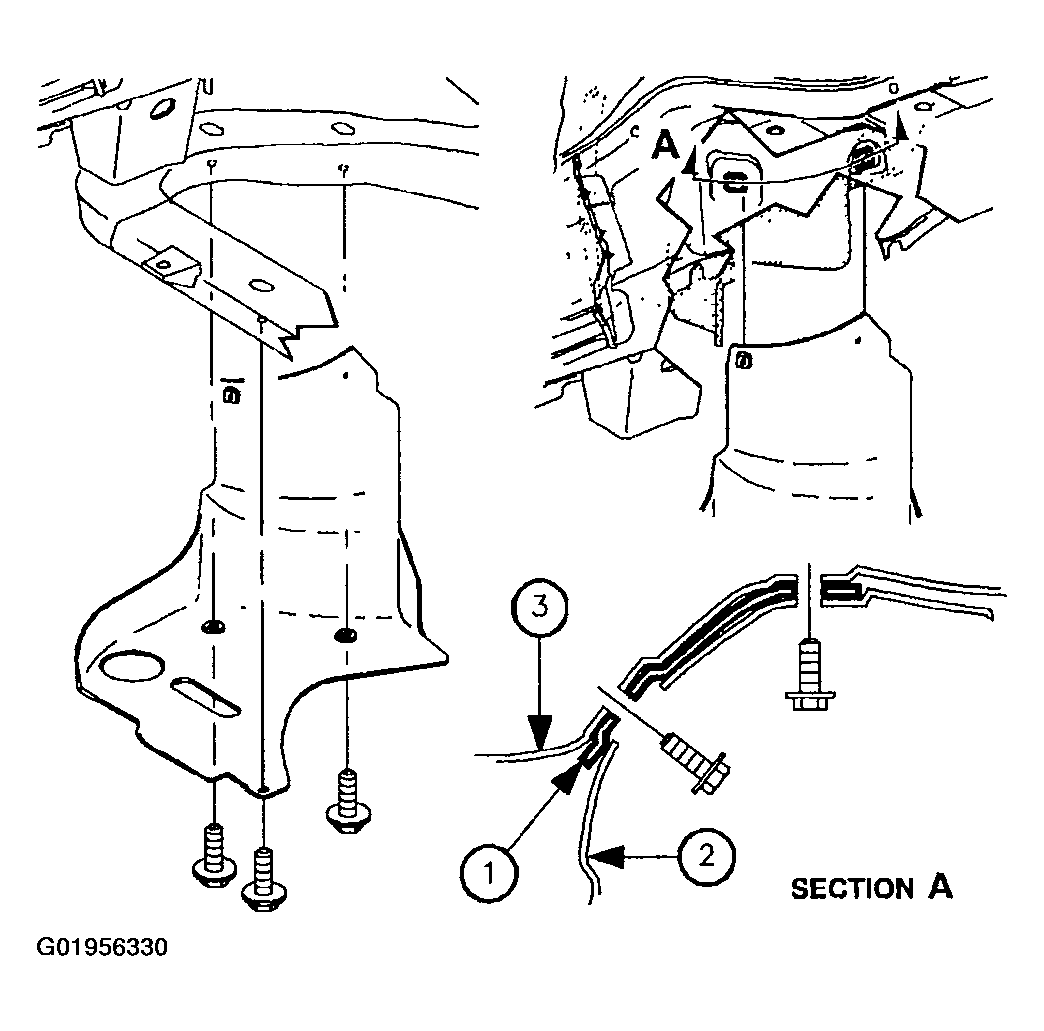
- Remove right front lower splash shield.
- Remove left front wheel liner push pin from frame.
 Courtesy of GENERAL MOTORS CORP.
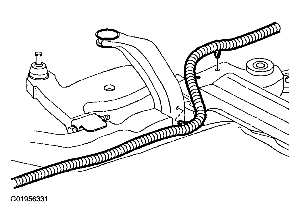
- Disconnect rear O2 sensor connection, and remove harness from frame at attachment points.
 Courtesy of GENERAL MOTORS CORP.
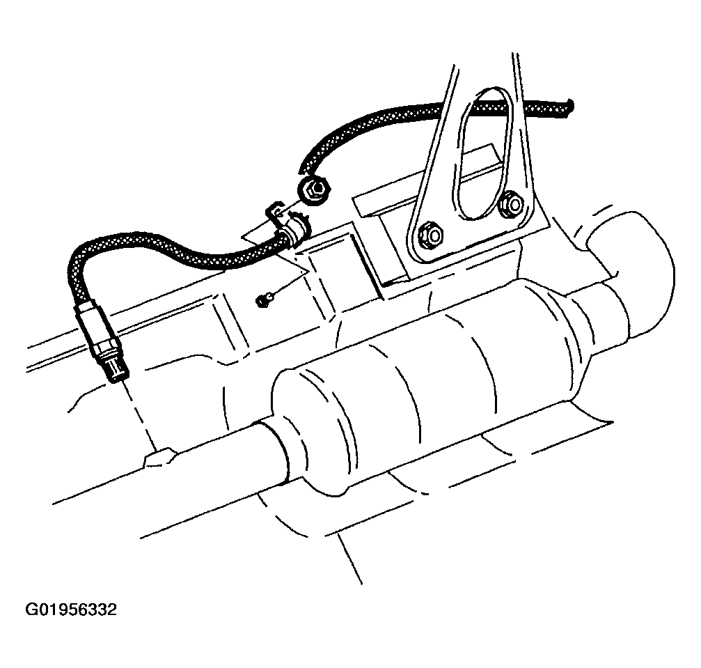
- On L61, remove O2 sensor clamp to underbody attachment nut.
 Courtesy of GENERAL MOTORS CORP.
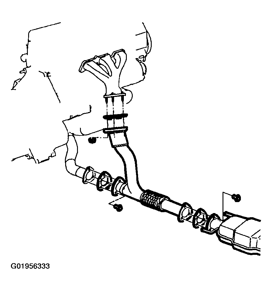
- Remove exhaust manifold pipe on L81 engines, and on L61 engines with manual transaxle. (L81 shown)
 Courtesy of GENERAL MOTORS CORP.
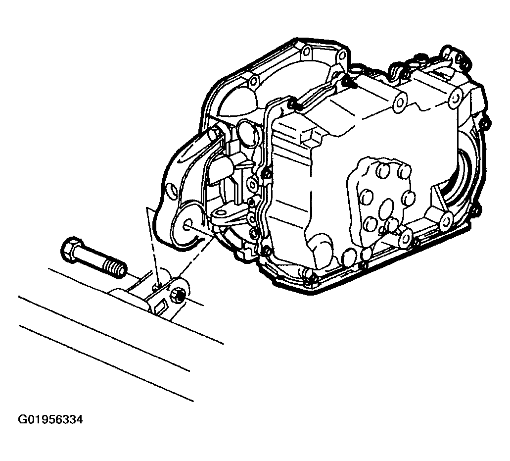
- Remove front transaxle mount through bolt.
 Courtesy of GENERAL MOTORS CORP.
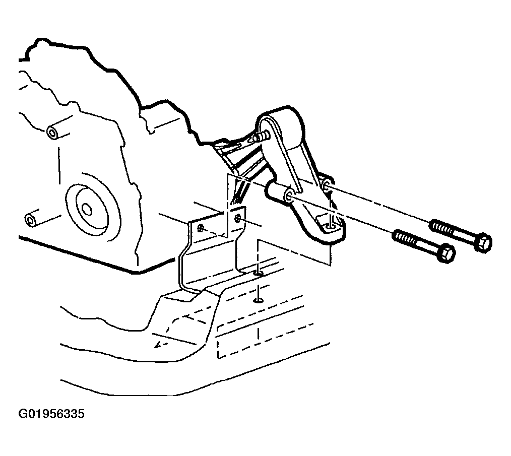
- Remove remaining rear transaxle mount-to-frame bolts.
- Remove rear transaxle mount.
 Courtesy of GENERAL MOTORS CORP.
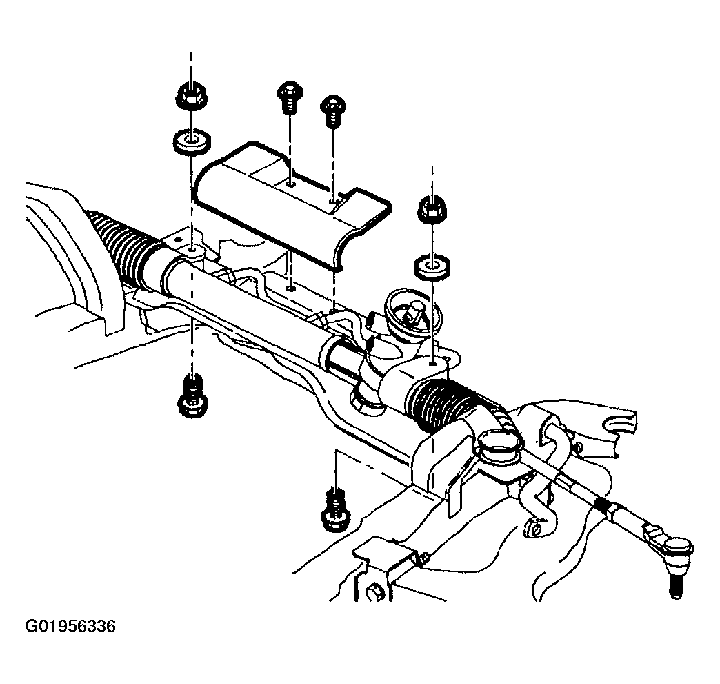
- Remove steering gear-to-frame bolts. Discard bolts and nuts.
- On vehicles equipped with L61 engines and automatic transaxle, remove steering gear heat shield.
- Using mechanics wire, secure the steering gear assembly to body of vehicle.
 Courtesy of GENERAL MOTORS CORP.
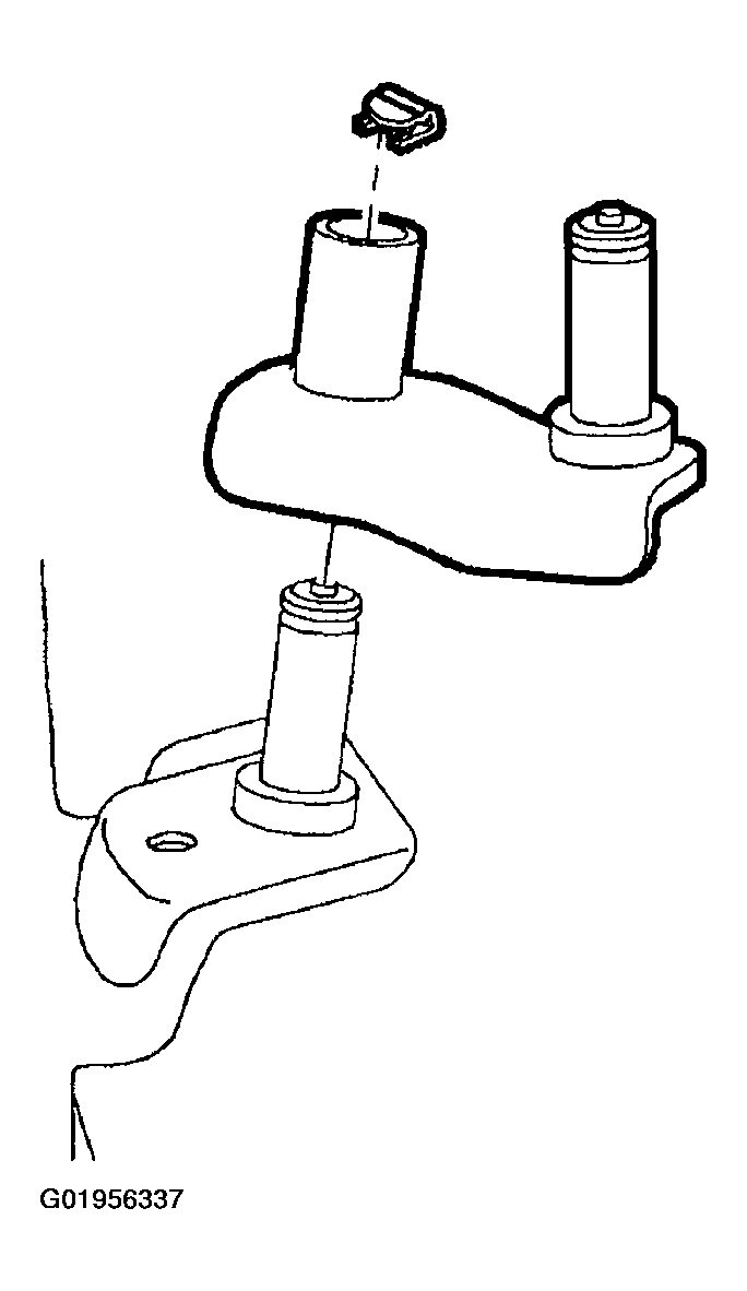
- On L61 with manual transaxle, remove frame to shifter link pivot pin clip.
 Courtesy of GENERAL MOTORS CORP.
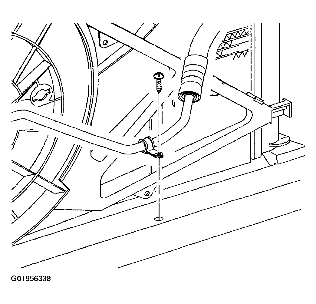
- Remove A/C line to frame attachment clip at front of vehicle.
 Courtesy of GENERAL MOTORS CORP.
CAUTION:
Hold ball stud from turning when removing nut. The boot can become torn and damaged if the ball stud turns.
- Remove stabilizer bar links from strut and discard nuts.
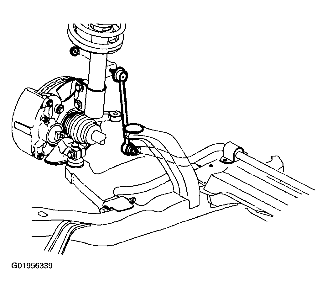 Courtesy of GENERAL MOTORS CORP.
CAUTION:
Do not attempt to separate joint using a wedge-type tool because seal may be damaged.
- Remove the lower ball stud bolt and separate the ball stud from the steering knuckle assembly.
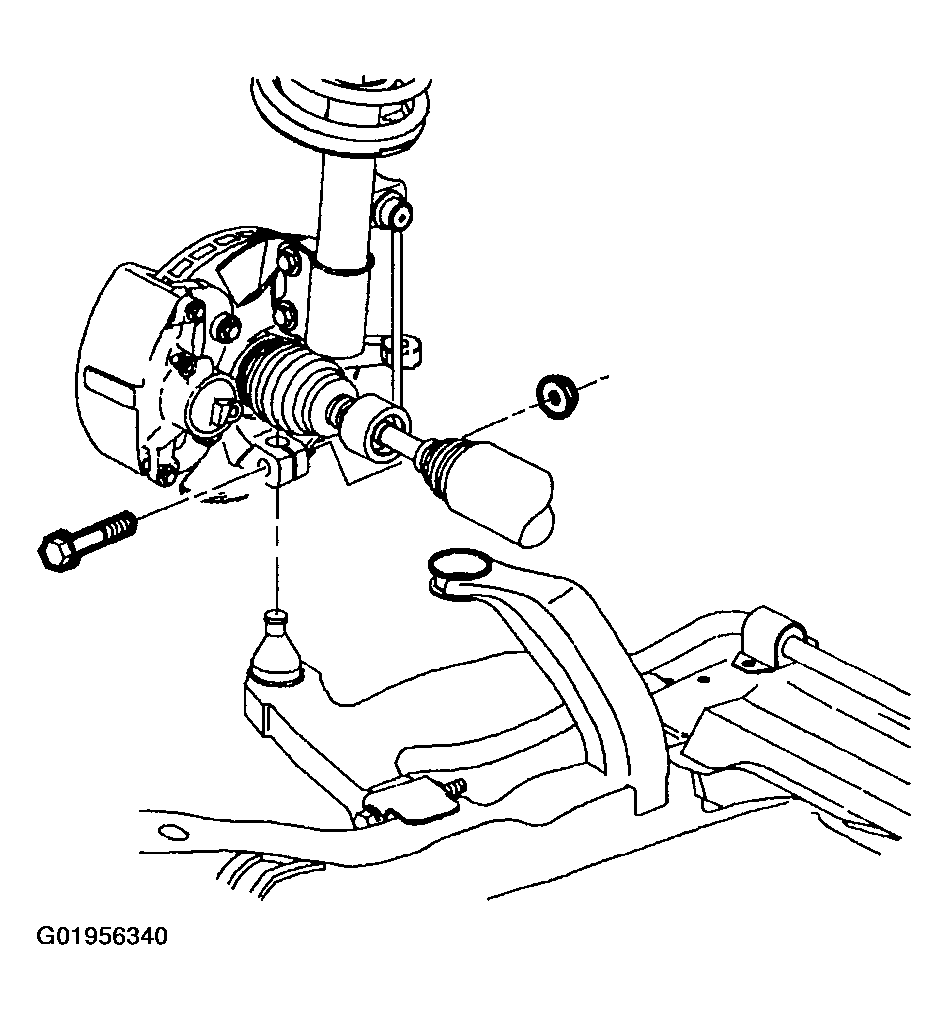 Courtesy of GENERAL MOTORS CORP.
- Remove the suspension support assemblies.
- Remove suspension support cage nuts from the body. Discard cage nuts and support bolts, as new nuts and bolts must be used for assembly.
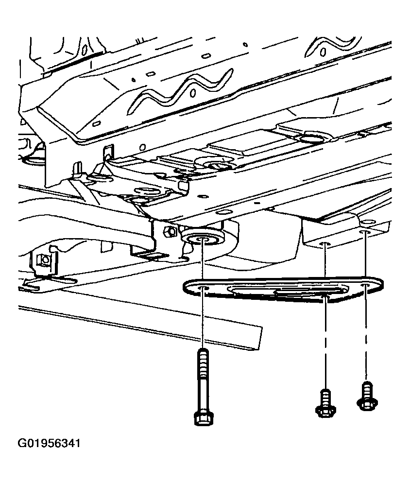 Courtesy of GENERAL MOTORS CORP.
- Using powertrain lifting table and the Frame Alignment Fixture J 43628, support frame assembly.
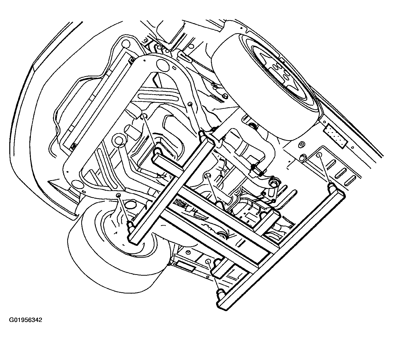 Courtesy of GENERAL MOTORS CORP.
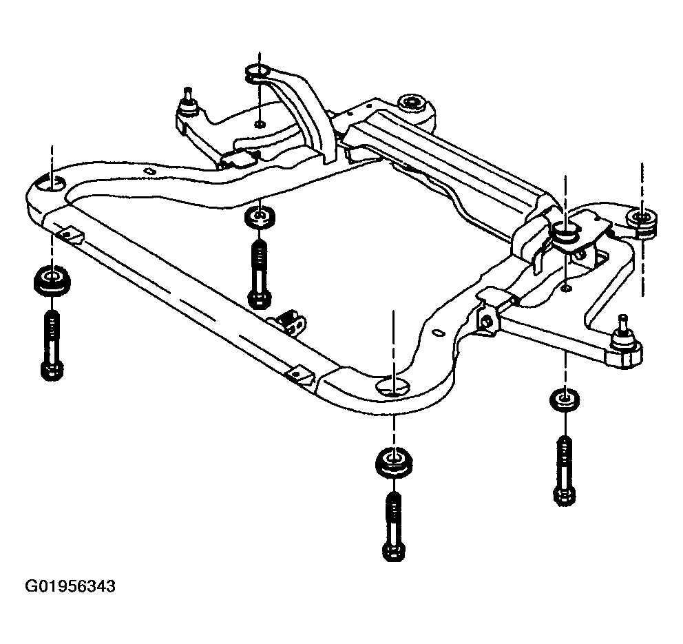
- Remove the remaining frame-to-body attachment fasteners.
- Carefully lower frame assembly from vehicle.
- Remove frame assembly cage nuts from body. Discard cage nuts and frame bolts as new nuts and bolts must be used for assembly.
 Courtesy of GENERAL MOTORS CORP.