Valve Body: Inspection
NOTE:
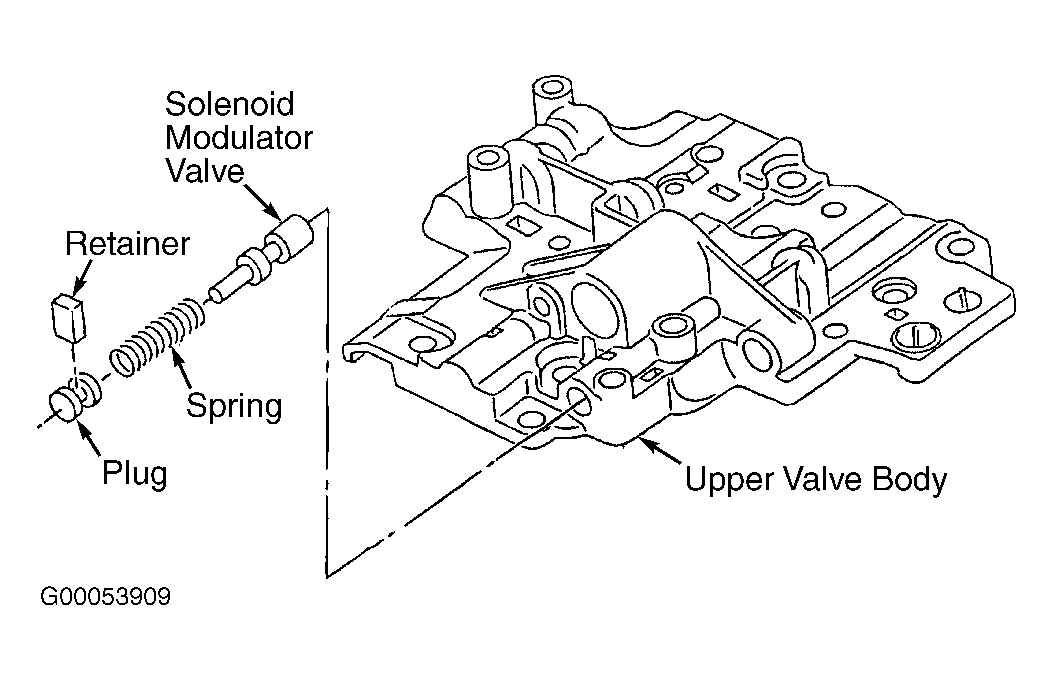
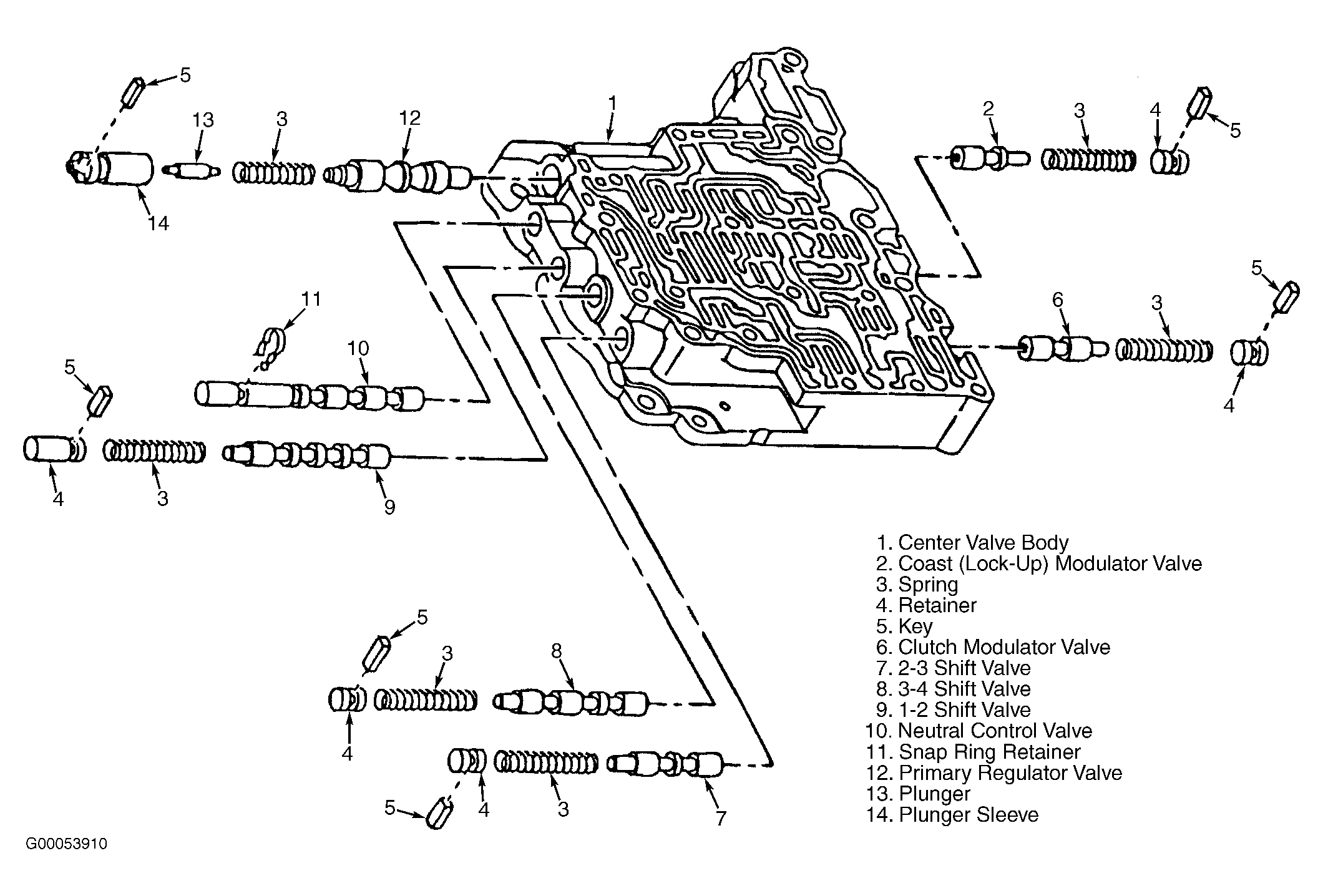
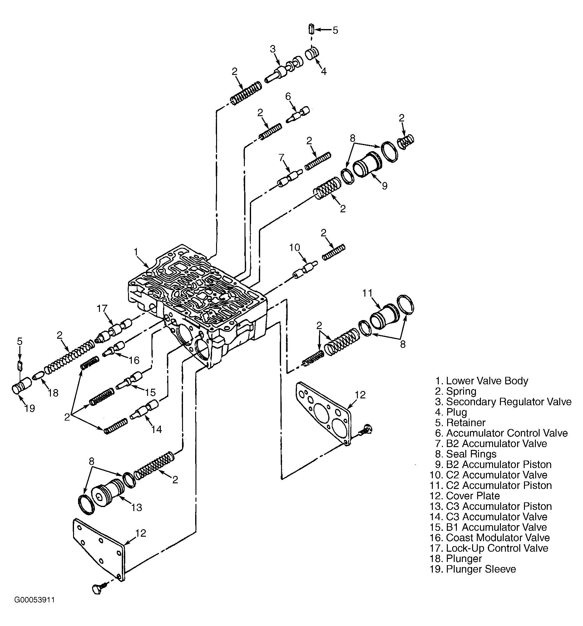
Valves may be held in with pins or retainers and plugs. Remove components and note locations. Arrange parts in order for reassembly reference.
- Individually remove valves. Clean all parts with solvent. Dry parts with compressed air. Ensure all valve body oil passages are clear. Inspect valves for scoring or roughness. Inspect valve springs for damage, squareness, rust and collapsed coils. Measure spring free length and outer diameter.
- Replace spring if not within specification. See VALVE BODY SPRING SPECIFICATIONS
table. Ensure valve body springs correspond with appropriate valve. Ensure retainers are installed in appropriate locations.
VALVE BODY SPRING SPECIFICATIONS
| Spring Description |
Diameter - In. (mm) |
Free Length - In. (mm) |
| Upper Valve Body |
| Solenoid Modulator Valve |
.315 (8.0) |
1.12 (28.53) |
| Center Valve Body |
| Primary Regulator Valve |
.41 (10.5) |
1.17 (29.72) |
| 1-2 Shift Valve |
.32 (8.2) |
1.30 (33.95) |
| 2-3 Shift Valve |
.32 (8.2) |
1.30 (33.95) |
| 3-4 Shift Valve |
.32 (8.2) |
1.30 (33.95) |
| Coast (Lock-Up) Modulator Valve |
.31 (8.0) |
.88 (22.42) |
| Clutch Modulator Valve |
.33 (8.3) |
.90 (22.78) |
| Lower Valve Body |
| Secondary Regulator Valve |
.39 (10.0) |
1.47 (37.4) |
| Accumulator Control Valve |
.28 (7.2) |
1.0 (26.6) |
| B2 Accumulator Valve |
.27 (7.0) |
1.3 (32.8) |
| B2 Accumulator Piston |
| Inner |
11.9 (.47) |
15.0 (.59) |
| Outer |
15.2 (.60) |
1.8 (46.0) |
| C2 Accumulator Valve |
.27 (7.0) |
1.2 (30.7) |
| C2 Accumulator Piston |
| Inner |
10.3 (.40) |
1.4 (.37) |
| Outer |
15.2 (.60) |
1.8 (46.0) |
| Lock-Up Control Valve |
.38 (9.6) |
2.5 (64.9) |
| Coast Modulator Valve |
.28 (7.2) |
.95 (24.4) |
| B1 Modulator Valve |
.31 (8.0) |
1.0 (25.9) |
| C3 Piston |
1.8 (46.0) |
.46 (11.6) |
| C3 Accumulator |
1.2 (30.7) |
.27 (7.0) |
 Courtesy of DAEWOO MOTOR AMERICA, INC.
 Courtesy of DAEWOO MOTOR AMERICA, INC.
 Courtesy of DAEWOO MOTOR AMERICA, INC.