Transaxle Disassembly
- Separate transaxle assembly from engine and mount on Transaxle Stand (78 60 794). Attach Torque Converter Support (87 90 255). Drain fluid from transaxle and final drive unit. Remove all 5 covers from assembly. Remove sealing ring from turbine shaft. Check for chain wear by measuring side deflection.
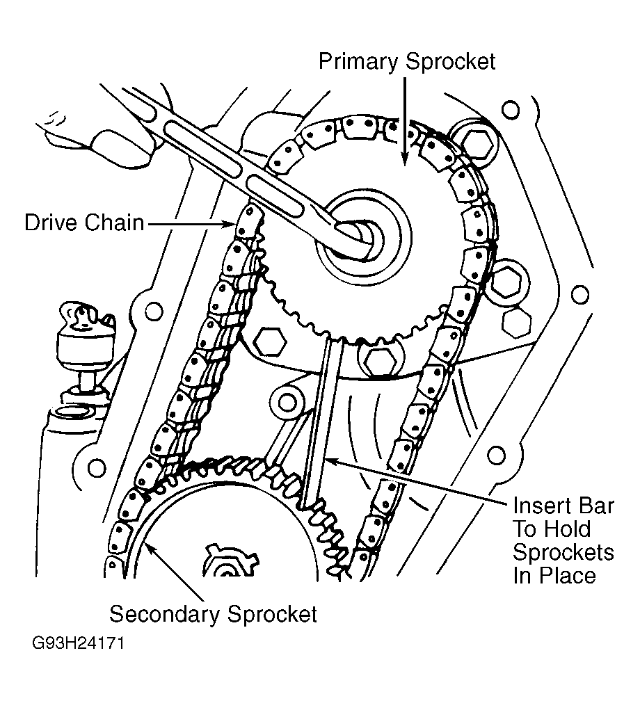
- Press chain outward toward case and measure distance between chain and case. Clearance should not be less than .393" (10.00 mm). If deflection exceeds specification, replace chain. Hold drive chain sprockets stationary using Bar (87 90 230) and remove sprocket attaching bolts. Remove drive chain and sprockets as an assembly. See Fig 1
.
- Turn transaxle upside down. Remove oil tubes No. 13, 14 and 15. Using Remover (87 91 360). See Figure
. Remove oil filter. Remove right and left side overflow pipes. Disconnect throttle valve cable. Remove all remaining oil tubes except 2 (No. 16 and 17) located from drain valve to servo piston. See Figure
.
- Note position of parking pawl. Remove valve body retaining bolts and lift out valve body. Remove neutral-drive accumulator piston and spring located under valve body. Remove 3rd-2nd drain valve and oil tubes No. 16 and 17. Remove accumulator plate and shift lever. Carefully tap 1st-2nd accumulator plunger with a hammer to remove with spring.
- Remove 10 torque converter housing-to-transaxle housing attaching bolts. Remove gear selector rod. Remove throttle cable. Remove torque converter and its support. Remove oil delivery pipes from pump. Remove clamp retaining bolt and remove suction pipe. Remove oil pump retaining bolts and oil pump.
- Remove snap ring and drive out front bearing. If necessary, heat case to ease removal. Remove shaft, lever and strut for front band. See Fig 2
. Release adjusting screw for rear band tension. Rotate ring gear so lower screw on governor is aligned with hook on parking pawl. Using Scribe (89 95 607), remove spring at support and at lever. Remove spring, shaft, lever, pin and strut.
- Attach sprocket and nut to input shaft. Tap sprocket to loosen cover and remove front clutch. Remove rear clutch assembly and sun gear shaft. Save shaft bearing and thrust washers for reassembly. Remove 3 bolts retaining center support.
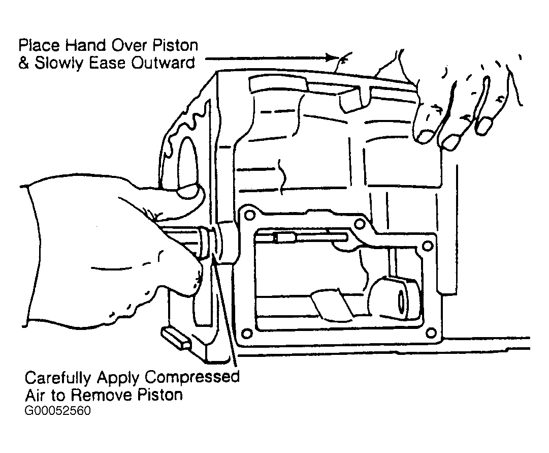
- Remove front bands, center support, planetary gear assembly and rear band. Remove front servo snap ring. Using compressed air, remove front and rear servo pistons. Place hand over piston and ease out gently. See Fig 3
.
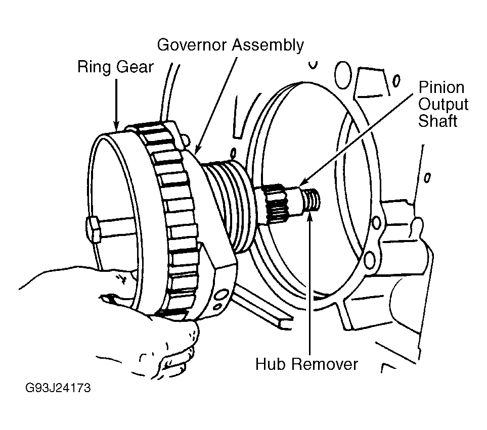
- Install Hub Remover (87 90 958) through middle of ring gear hub. Slowly tighten bolt and pull hub, governor and pinion output shaft. See Fig 4
. Use parking pawl to hold hub during removal. DO NOT remove parking pawl unless it is to be replaced. If necessary, remove snap ring from pivot shaft, push out shaft and remove pawl and spring.
NOTE:
Before disassembling final drive unit, measure and record backlash and position of pinion for reassembly reference. See procedure under TRANSAXLE REASSEMBLY
. If ring and pinon gear assembly have been installed for less than 6000 miles, follow normal adjustment procedures on reassembly. If assembly has been installed for longer than 6000 miles, adjust to recorded measurements.
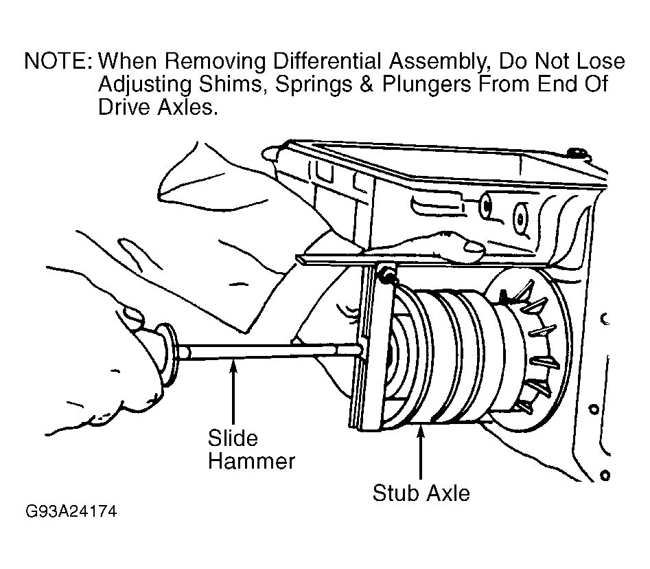
- Remove differential bearing housing retaining bolts from both sides. Using Puller (87 90 776) and Slide Hammer (83 90 270), remove bearing housings and axle shafts. Remove differential assembly from case. See Fig 5
.
- Remove pinion bearing housing retaining bolts. Place transaxle housing in press and press out pinion bearing housing and pinion seal housing (pressure applied at seal housing).
 Courtesy of SAAB-SCANIA OF AMERICA, INC.
 Courtesy of SAAB-SCANIA OF AMERICA, INC.
 Courtesy of SAAB-SCANIA OF AMERICA, INC.
 Courtesy of SAAB-SCANIA OF AMERICA, INC.
 Courtesy of SAAB-SCANIA OF AMERICA, INC.