Installation Procedure
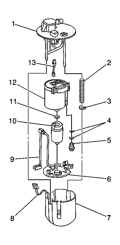 Courtesy of GENERAL MOTORS CORP.
- Lubricate all O-rings (4, 11) with fuel during assembly. Use the exploded view to aid in assembly.
 Courtesy of GENERAL MOTORS CORP.
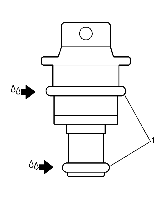
- Install 2 new O-rings (1) onto the fuel pressure regulator.
 Courtesy of GENERAL MOTORS CORP.
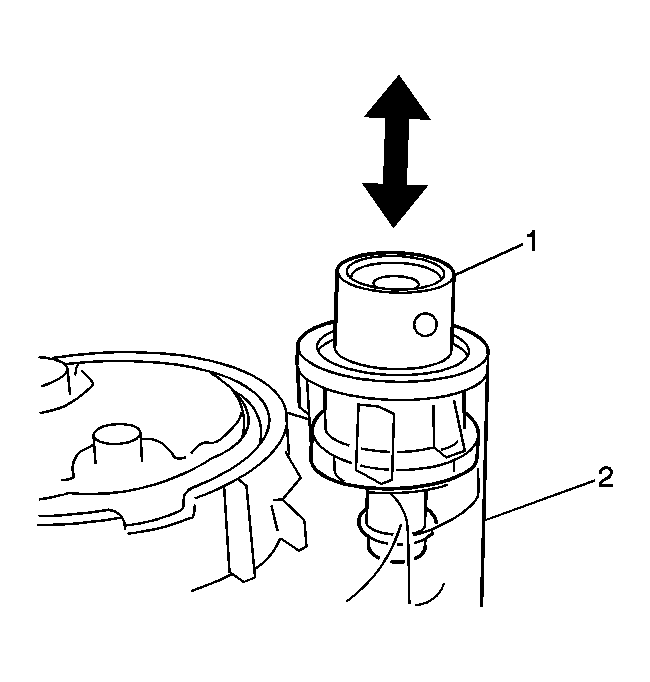
- Install the fuel pressure regulator (1) into the fuel filter assembly (2).
 Courtesy of GENERAL MOTORS CORP.
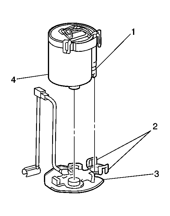
- Align the 2 lock tabs (2) with the fuel pressure regulator (1) and install the fuel pump strainer assembly (3) onto the fuel filter assembly (4).
 Courtesy of GENERAL MOTORS CORP.
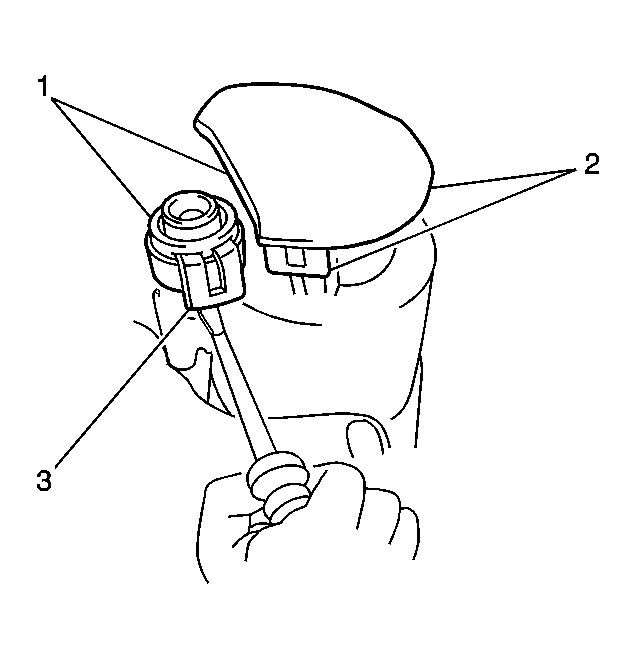
- Secure the strainer assembly to the filter assembly with the 5 lock tabs (1, 2, 3).
 Courtesy of GENERAL MOTORS CORP.
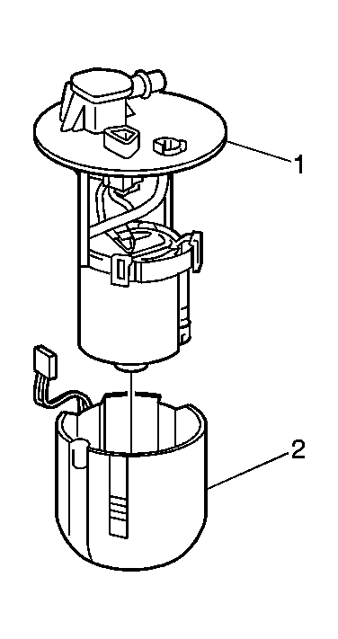
- Install the lower housing (2) to the fuel pump filter and upper support assemblies (1).
 Courtesy of GENERAL MOTORS CORP.
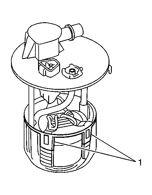
- Secure the lower and upper assemblies using the 2 lock tabs (1).
 Courtesy of GENERAL MOTORS CORP.
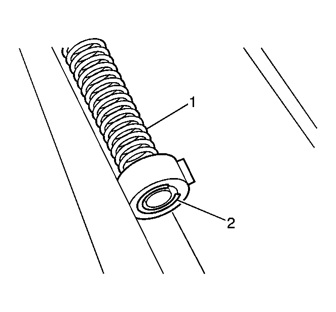
- With the upper support guide posts correctly aligned with lower housing, gently compress the spring (1) and install a new E-clip (2).
 Courtesy of GENERAL MOTORS CORP.
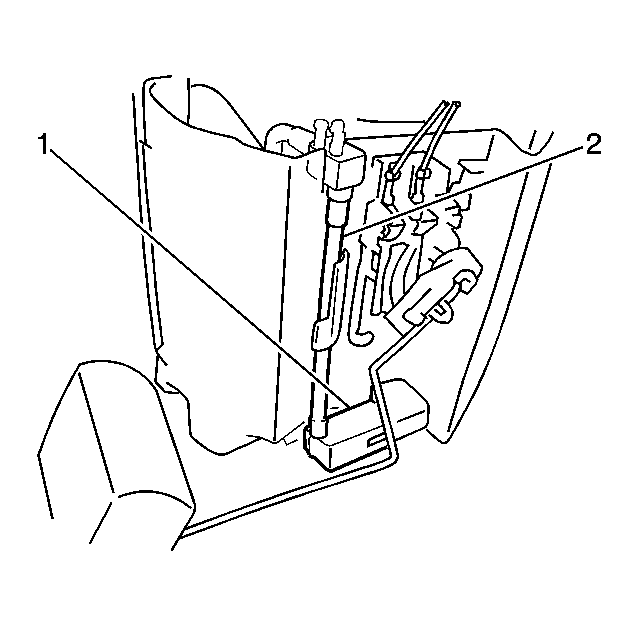
- Connect the jet tube (2) to the lower housing fuel inlet port (1) and secure with the lock tab.
 Courtesy of GENERAL MOTORS CORP.
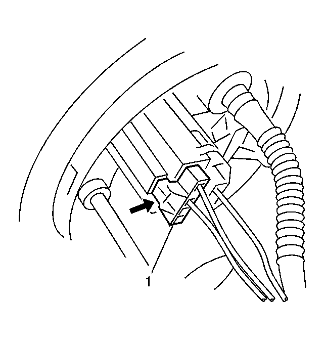
- Connect the fuel pump and fuel level sensor (1) electrical connectors.
- Install the fuel sender assembly into the fuel tank. Refer to Fuel Sender Assembly Replacement (FWD) or Fuel Sender Assembly Replacement (AWD) .