Test A: Power Mirrors Inoperative: Notes
- Review DESCRIPTION & OPERATION
, then go to next step.
- Set outside rearview mirror switch to LEFT position. Activate position switch to UP, DOWN, LEFT and RIGHT positions and note operation. Set outside rearview mirror switch to RIGHT position. Activate position switch to UP, DOWN, LEFT and RIGHT positions and note operation. If both mirrors operate properly, check for intermittent or poor connections. Repair as necessary. If both/either mirror(s) do not operate properly, go to next step.
- If both mirrors are completely inoperative, go to next step. If both mirrors are not completely inoperative, go to step 6
.
- Disconnect outside rearview mirror switch Black 8-pin harness connector. Using a test light connected to ground, probe outside rearview mirror switch harness connector terminal "E" (Orange wire). If test light illuminates, go to next step. If test light does not illuminate, go to step 7
.
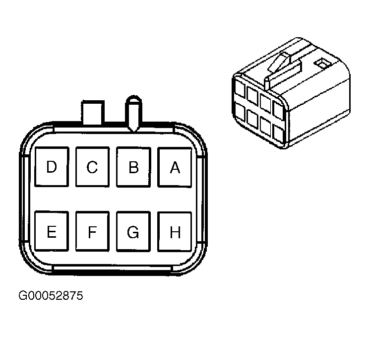 Courtesy of GENERAL MOTORS CORP.
- Connect test light between outside rearview mirror switch harness connector terminals "D" (Black wire) and terminal "E" (Orange wire). If test light illuminates, go to step 9
. If test light does not illuminate, go to step 15
.
- Disconnect suspect mirror harness connector. Connect a test light between appropriate mirror motor harness connector control circuit terminals. Set outside rearview mirror switch to mirror to be tested. Activate mirror in both directions for inoperative function. If test light does not illuminate in both directions, go to step 8
. If test light illuminates in both directions, go to step 12
.
- Check for an open or short to ground in Orange wire (battery voltage circuit) between instrument panel fuse block and outside rearview mirror switch harness connector terminal "E". If Orange wire is okay, go to step 9
. If Orange wire is not okay, repair as necessary. After repair, go to step 18
.
- Check for an open in suspect mirror motor control circuits. If circuits are okay, go to next step. If circuits are not okay, repair as necessary. After repair, go to step 18
.
- Reconnect mirror connector(s). Ensure outside rearview mirror switch harness connector is disconnected. Using a test light connected to positive battery voltage, probe each power mirror motor control circuits at outside rearview mirror switch harness connector. If test light does not illuminate at any power mirror motor control circuit, go to next step. If test light illuminates at any power mirror control circuit, go to step 13
.
- Using a test light connected to ground, probe each power mirror motor control circuit of outside rearview mirror switch harness connector. See WIRING DIAGRAMS
. If test light does not illuminate at any power mirror motor circuit, go to next step. If test light illuminates at any power mirror motor circuit, go to step 14
.
- Check outside rearview mirror switch connector for intermittent or poor terminal contact. If terminal contact is okay, go to step 16
. If terminal contact is not okay, repair as necessary. After repair, go to step 18
.
- Check suspect power mirror connector for intermittent or poor terminal contact. If terminal contact is okay, go to step 17
. If terminal contact is not okay, repair as necessary. After repair, go to step 18
.
- Repair short to ground in appropriate in power mirror motor control circuit(s). After repair, go to step 18
.
- Repair short to voltage in appropriate power mirror motor control circuit(s). After repair, go to step 18
.
- Repair open in outside rearview mirror switch ground circuit (Black wire) between outside rearview mirror switch and ground. Ground point is located inside left door sill, forward of left front seat. After repair, go to step 18
.
- Replace outside rearview mirror switch. After repair, go to step 18
.
- Replace appropriate power mirror motor(s). After repair, go to next step.
- Operate system to verify fault no longer exists. If fault still exists, go to step 2
.
 Courtesy of GENERAL MOTORS CORP.