Transaxle Case Cover & Input Unit Assembly
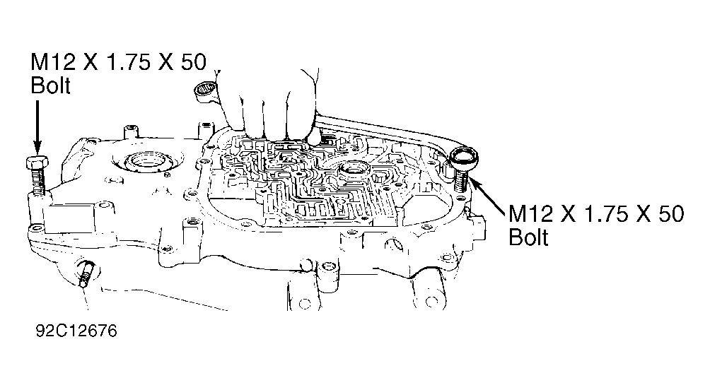
- Disconnect manual valve rod from manual valve. Remove remaining transmission case cover mount bolts. Install 2 bolts (12 x 1.75 x 50 mm) into case cover dowel pin holes. See Fig 1
.
- Bolts will bottom out on dowel pins and separate case cover from case. DO NOT
pry cover from case. Remove case cover, and lay side with 1-2 accumulator up, as 1-2 accumulator pin may drop out of cover.
- Remove 1-2 accumulator spring, piston and center case-to-cover gasket. Remove case cover-to-drive sprocket thrust washer and driven sprocket thrust bearing assembly. Case cover-to-drive sprocket thrust washer may come off with case cover.
- Remove and discard turbine shaft "O" ring. Remove drive sprocket, driven sprocket and chain as an assembly. See Figure
. Remove drive and driven sprocket-to-support thrust washers. These washers may come off with sprockets.
 Courtesy of GENERAL MOTORS CORP.
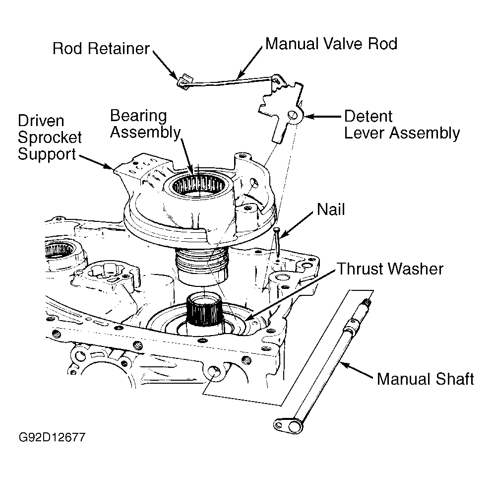
- Using 3/16" drift, remove detent lever-to-manual shaft pin. Remove manual shaft-to-case nail. See Fig 2
. Withdraw manual shaft from case, and lift out manual valve rod and detent lever assembly. Remove park lock actuator rod.
- Remove driven sprocket support and thrust washer on direct clutch side. See Fig 2
. Thrust washer may come out with driven sprocket support. Remove intermediate band anchor hole plug and intermediate band assembly.
- While lifting input shaft, remove and separate direct and forward clutch assemblies. Remove input internal gear-to-input shaft thrust washer, and remove input internal gear.
- Remove input carrier assembly, input carrier-to-input internal gear thrust washer and input carrier-to-input sun gear thrust washer. Remove input sun gear and input drum.
 Courtesy of GENERAL MOTORS CORP.