System Check
- Ensure power door lock system operates correctly. Access RKE module. See REMOVAL & INSTALLATION
. Disconnect module harness connectors.
- Using ohmmeter, check for continuity between terminals No. 1 and 4 of Gray harness connector. See Fig 1
. If continuity exists, go to next step. If continuity does not exist, inspect and repair circuits as needed. See WIRING DIAGRAM
.
- Check for continuity between terminals No. 2 and 3 of Gray harness connector. See Fig 1
. If continuity exists, go to next step. If continuity does not exist, inspect and repair circuits as needed. See WIRING DIAGRAM
.
- Check for continuity between terminal No. 1 of Black connector and No. 3 of Gray harness connector. See Fig 1
. If continuity exists, go to next step. If continuity does not exist, inspect and repair circuits as needed. See WIRING DIAGRAM
.
- Check for continuity between terminal No. 3 of Black connector and ground. See Fig 1
. If continuity exists, go to next step. If continuity does not exist, inspect and repair circuits as needed. See WIRING DIAGRAM
.
- Ensure ignition is off. Using voltmeter, measure voltage between terminal No. 2 of Black connector and ground. If battery voltage is present, go to next step. If battery voltage is not present, inspect and repair circuit as needed. See WIRING DIAGRAM
.
- Turn ignition on. Measure voltage between terminal No. 8 of Black connector and ground. If battery voltage is present, go to next step. If battery voltage is not present, inspect and repair circuit as needed. See WIRING DIAGRAM
.
- Ensure transmitter batteries are okay. Replace as needed. Ensure transmitter(s) is programmed. See TRANSMITTER PROGRAMMING
. If transmitter programming is not possible, check continuity of programming line. Repair as needed. See WIRING DIAGRAM
.
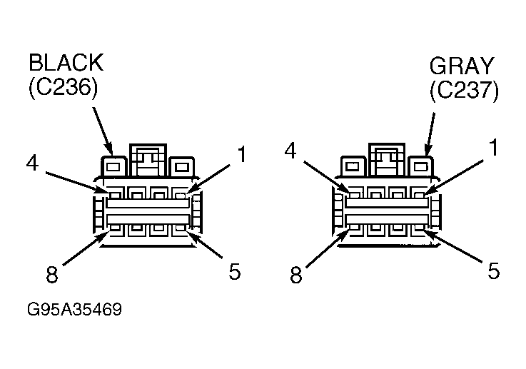 Courtesy of CHRYSLER CORP.