System Check
- Ensure power door lock system operates correctly. Access RKE module. See REMOVAL & INSTALLATION. Disconnect module harness connectors.
- Using ohmmeter, check for continuity between terminals No. 1 and 4 of Gray harness connector. See Fig 1
. If continuity exists, go to next step. If continuity does not exist, inspect and repair circuits as needed. See WIRING DIAGRAM.
- Check for continuity between terminals No. 2 and 3 of Gray harness connector. See Fig 1
. If continuity exists, go to next step. If continuity does not exist, inspect and repair circuits as needed. See WIRING DIAGRAM.
- Check for continuity between terminal No. 1 of Black connector and No. 3 of Gray harness connector. See Fig 1
. If continuity exists, go to next step. If continuity does not exist, inspect and repair circuits as needed. See WIRING DIAGRAM.
- Check for continuity between terminal No. 3 of Black connector and ground. See Fig 1
. If continuity exists, go to next step. If continuity does not exist, inspect and repair circuits as needed. See WIRING DIAGRAM.
- Ensure ignition is off. Using voltmeter, measure voltage between terminal No. 2 of Black connector and ground. If battery voltage is present, go to next step. If battery voltage is not present, inspect and repair circuit as needed. See WIRING DIAGRAM.
- Turn ignition on. Measure voltage between terminal No. 8 of Black connector and ground. If battery voltage is present, go to next step. If battery voltage is not present, inspect and repair circuit as needed. See WIRING DIAGRAM.
- Ensure transmitter batteries are okay. Replace as needed. Ensure transmitter(s) is programmed. See TRANSMITTER PROGRAMMING. If transmitter programming is not possible, check continuity of programming line. Repair as needed. See WIRING DIAGRAM.
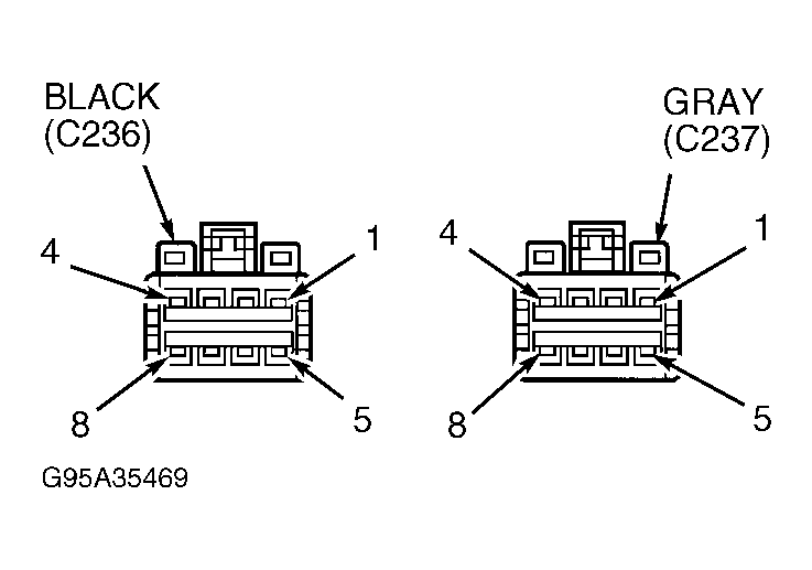 Courtesy of CHRYSLER CORP.