System Test
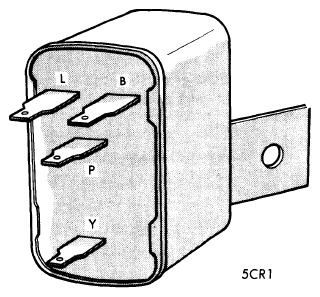
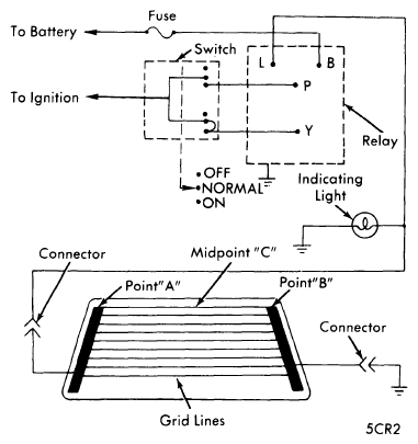
- Check that in-line fuses~ or circuit breakers are operational and supply power. With rear window grid lines disconnected, turn ignition switch on and check voltage at relay terminals. Terminals "B" and "Y" should have voltage and terminals "L" and "P" should not have voltage (see illustration).
 Courtesy of CHRYSLER GROUP, LLC
- Unplug relay and ground case. Connect a jumper wire between terminals "B" and "Y" and a 12 volt test light between terminal "L" and ground. Apply voltage to terminal "B". Test light should not light, if it does replace relay. Momentarily short terminals "B" and "P". Test light should come on and stay on after short is removed for 8.5-11.5 minutes if it has a timer or continuous if it does not.
 Courtesy of CHRYSLER GROUP, LLC
- Disconnect switch wires. With switch in "NORMAL" position, there should be continuity between two terminals. With switch "ON" there should be continuity between all terminals. With switch "OFF" there should be no continuity between terminals.
- If system still does not operate, check leads and grid lines at rear window. Turn ignition and control switches on, attach a voltmeter between points "A" and "B" (see illustration). Voltage reading should be 10-14 volts, if lower, check ground connections. With a voltmeter connected at "B", measure grid voltages at midpoint "C". Voltage should be approximately six volts, a reading of zero volts indicates a break between point "A" and midpoint "C". A reading of 12-13 volts indicates a break between midpoint "C" and "B".