Diagnostic Procedures
- If powertrain diagnostic system check has already been performed, go to next step. If powertrain diagnostic system check has not been performed, go to POWERTRAIN DIAGNOSTIC SYSTEM CHECK under DIAGNOSTIC SYSTEM CHECKS.
- Turn ignition on. Using scan tool, observe TP sensor angle parameter while slowly opening throttle to WOT. If TP sensor angle increased steadily from zero percent to 98 percent, go to next step. If TP sensor angle did not increase steadily from zero percent to 98 percent, go to step 4.
- Using scan tool, observe and record FREEZE FRAME/FAILURE RECORDS data for this DTC. Turn ignition off for 30 seconds. Start engine. Operate vehicle within conditions for running the DTC as specified in code enable criteria, or as close to recorded FREEZE FRAME/FAILURE RECORDS data as possible. If DTC resets, go to next step. If DTC does not reset, see DIAGNOSTIC AIDS .
- Turn ignition off. Disconnect TP sensor connector. Turn ignition on. Using scan tool, observe TP sensor voltage. If voltage is zero volts, go to next step. If voltage is not zero volts, to step 6.
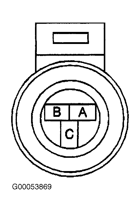
- Turn ignition off. Connect a 3-amp fused jumper wire between terminal "A" (Gray wire) and terminal "C" (Dark Blue wire) at TP sensor harness connector. See Fig 1. Using scan tool, observe TP sensor voltage. If voltage is 5 volts, go to step 9. If voltage is not 5 volts, go to step 7.
 Courtesy of GENERAL MOTORS CORP.
- Turn ignition off. Disconnect PCM connectors. PCM is located in left front corner of engine compartment, inside air filter housing. Turn ignition on. Measure voltage between ground and terminal No. 66 (Dark Blue wire) at PCM C2 harness connector. See Figure. If any voltage is indicated, repair short to voltage in Dark Blue wire. After repairs, go to 14. If no voltage is indicated, go to step 12.
- Turn ignition off. Check continuity of Gray wire between terminal "A" at TP sensor harness connector and terminal No. 33 at PCM C2 harness connector. See Figure and Fig 1
. If continuity exists, go to next step. If continuity does not exist, repair open in Gray wire. After repairs, go to step 14.
- Check continuity of Dark Blue wire between terminal "C" at TP sensor harness connector and terminal No. 66 at PCM C2 harness connector. If continuity exists, go to step 11. If continuity does not exist, repair open in Dark Blue wire. After repairs, go to step 14.
- Check continuity of Black wire between terminal "B" at TP sensor harness connector and terminal No. 61 at PCM C1 harness connector. If continuity exists, go to next step. If continuity does not exist, repair open in Black wire. After repairs, go to step 14.
- Check for poor connections at TP sensor connector. Repair connector as necessary. After repairs, go to step 14. If connector is okay, go to step 12.
- Check for poor connections at PCM connectors. Repair connectors as necessary. After repairs, go to step 14. If connectors are okay, go to step 13.
- Replace TP sensor. After repairs, go to step 14.
- Replace PCM. Program replacement PCM. See PROGRAMMING . After repairs, go to next step.
- Turn ignition off. Reconnect all disconnected connectors. Turn ignition on. Using scan tool, clear DTCs. Turn ignition off for 30 seconds. Start engine. Operate vehicle within conditions for running the DTC as specified in code enable criteria. If DTC runs and passes, go to next step. If DTC resets, go to step 2.
- Using scan tool, check for any other DTCs that are set. If no other DTCs are set, test is complete. If any other DTCs are set, repair DTCs as necessary. See DIAGNOSTIC TROUBLE CODE DEFINITIONS .