Component Parts Location
WARNING: This page is about a different car, the 2015 Nissan Murano. However, it is still accessible from the selected car via links, so may be relevant.
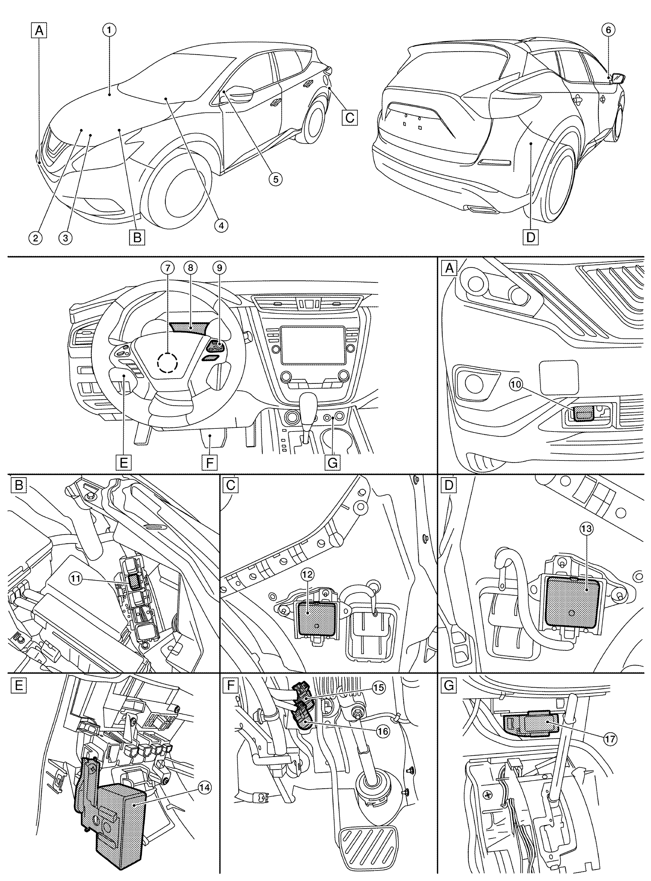 Courtesy of NISSAN NORTH AMERICA, INC.
| A. |
Front Bumper RH |
B. |
Engine Room LH |
C. |
Rear Bumper LH |
| D. |
Rear Bumper RH |
E. |
View With Instrument Lower Panel LH Removed |
F. |
Upper Side Of Brake Pedal Assembly |
| G. |
View With Center Console Assembly Removed |
|
|
|
|
| No. |
Component |
Description |
| 1. |
BCM |
- Transmits the turn indicator signal and position light request signal to ADAS control unit via CAN communication.
- Refer to COMPONENT PARTS LOCATION
for detailed installation location.
|
| 2. |
ABS actuator and electric unit (control unit) |
- ABS actuator and electric unit (control unit) transmits the vehicle speed signal (wheel speed), stop lamp signal and VDC/TCS/ABS system operation condition to ADAS control unit via CAN communication.
- ABS actuator and electric unit (control unit) controls the brake, based on a brake fluid pressure control signal received from ADAS control unit via CAN communication.
- Refer to COMPONENT PARTS LOCATION
for detailed installation location.
|
| 3. |
ECM |
- Transmits the ICC brake switch signal, stop lamp switch signal, ICC steering switch signal, etc. to ADAS control unit via CAN communication.
- Refer to COMPONENT PARTS LOCATION
for detailed installation location.
|
| 4. |
TCM |
- TCM transmits the signal related to CVT control to ADAS control unit.
- Refer to COMPONENT PARTS LOCATION
for detailed installation location.
|
| 5. |
Blind Spot Warning indicator LH |
Refer to BLIND SPOT WARNING INDICATOR LH/RH . |
| 6. |
Blind Spot Warning indicator RH |
| 7. |
Steering angle sensor |
- Measures the rotation amount, rotation speed, and rotation direction of steering wheel, and then transmits them to ADAS control unit via CAN communication.
- Refer to COMPONENT PARTS LOCATION
for detailed installation location.
|
| 8. |
Combination meter |
|
| 9. |
ICC steering switch |
Refer to ICC STEERING SWITCH . |
| 10. |
ICC sensor |
Refer to ICC SENSOR . |
| 11. |
ICC brake hold relay |
Refer to ICC BRAKE HOLD RELAY . |
| 12. |
Side radar LH |
Refer to SIDE RADAR LH/RH . |
| 13. |
Side radar RH |
| 14. |
Warning buzzer |
Refer to WARNING BUZZER . |
| 15. |
Stop lamp switch |
Refer to BRAKE PEDAL POSITION SWITCH / STOP LAMP SWITCH . |
| 16. |
Brake pedal position switch |
| 17. |
ADAS control unit |
- ADAS control unit controls each system (ICC/PFCW/FEB/BSW/RCTA), based on ITS communication signals and CAN communication signals from each control unit.
- ADAS control unit transmits engine torque command value, brake fluid pressure control signal, and buzzer output signal to each units.
|