- Mount the engine on a suitable engine stand.
- Drain any remaining engine oil and coolant from the engine.
- Remove the following components and associated parts.
- Remove the cylinder block heater, if equipped.
- Remove the knock sensor.
CAUTION:
Carefully handle the sensor and do not drop the sensor.
- Remove crankshaft position sensor (POS).
CAUTION:
- Avoid impacts such as a dropping.
- Do not disassemble.
- Keep it away from metal particles.
- Do not place sensor close to magnetic materials.
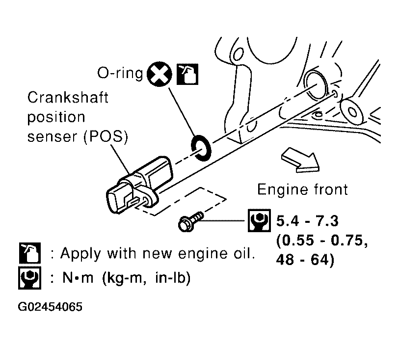 Courtesy of NISSAN MOTOR CO., U.S.A.
- Remove the flywheel (M/T models) or drive plate (A/T models). Hold the crankshaft with a stopper plate and remove the mounting bolts using Tool.
- Tool numbers
- For Flywheel bolt: J-45737
- For Drive plate bolt: J-45816
CAUTION:
- Be careful not to damage the flywheel contact surface for the clutch disc.
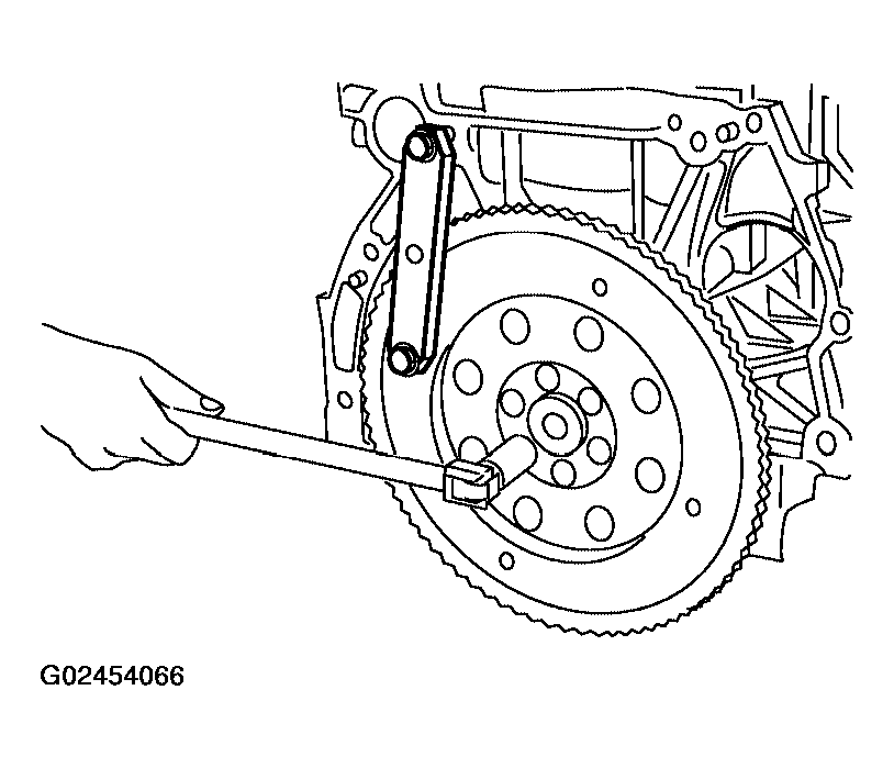 Courtesy of NISSAN MOTOR CO., U.S.A.
NOTE:
- The flywheel two-block construction allows movement in response to transmission side pressure, or when twisted in its rotational direction, therefore, some amount of noise is normal.
- Remove pilot converter using Tool (A/T models).
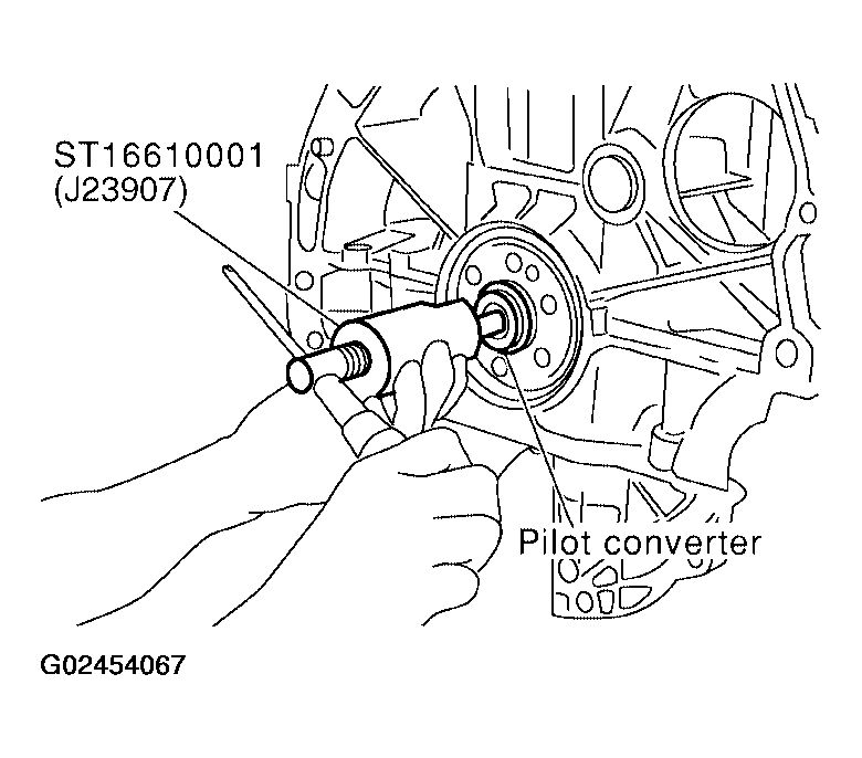 Courtesy of NISSAN MOTOR CO., U.S.A.
- Remove the piston and connecting rod assemblies.
- Position the crankshaft and corresponding connecting rod, to be removed, to the bottom dead center stroke.
- Remove the connecting rod cap. Number the cap so it can be assembled in the same position.
- Using a hammer handle or similar tool, push the piston and connecting rod assembly out of the top of the cylinder block. Number the piston and rod so it can be assembled in the same position.
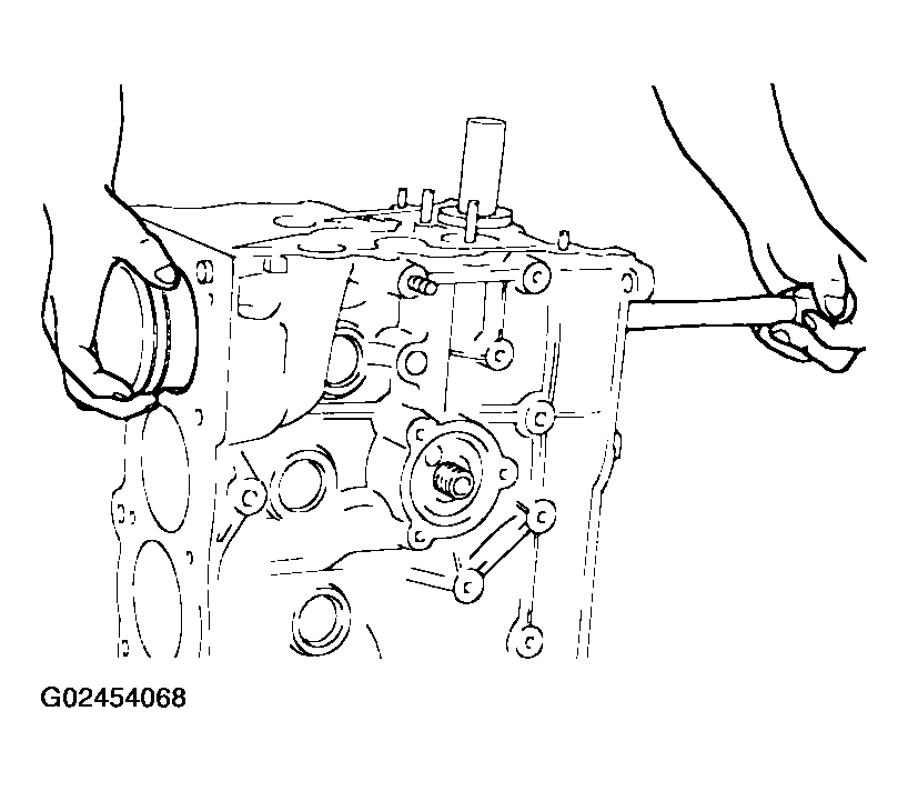 Courtesy of NISSAN MOTOR CO., U.S.A.
- Remove the connecting rod bearings. If reusing, number them so they can be assembled in the same position and direction.
CAUTION:
- When removing them, note the installation position. Keep them in the correct order.
- Remove the piston rings from the piston.
- Use a piston ring expander.
- Before removing the piston rings, check the piston ring side clearance. Refer to PISTON RING SIDE CLEARANCE .
CAUTION:
- When removing the piston rings, be careful not to damage the piston.
- Be careful not to damage piston rings by expanding them excessively, if reusing them.
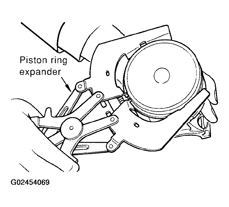 Courtesy of NISSAN MOTOR CO., U.S.A.
- Remove the piston from the connecting rod as follows:
- Using a snap ring pliers, remove the two snap rings.
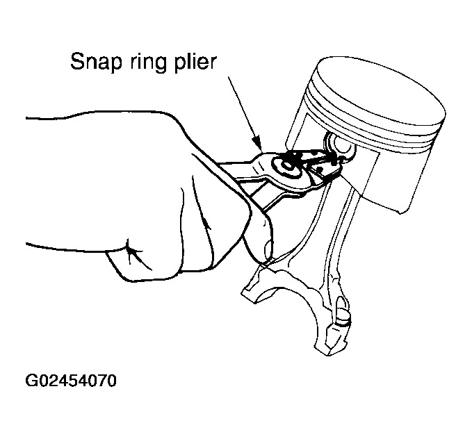 Courtesy of NISSAN MOTOR CO., U.S.A.
- Heat the piston to 60° - 70°C (140° - 158°F) with a heat gun, or equivalent.
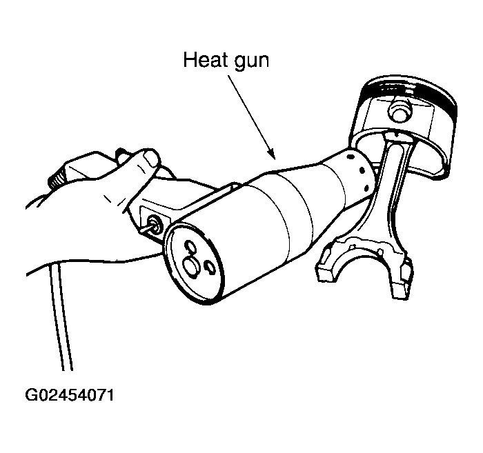 Courtesy of NISSAN MOTOR CO., U.S.A.
- Push out piston pin with a punch of an outer diameter of approximately 19 mm (0.75 in).
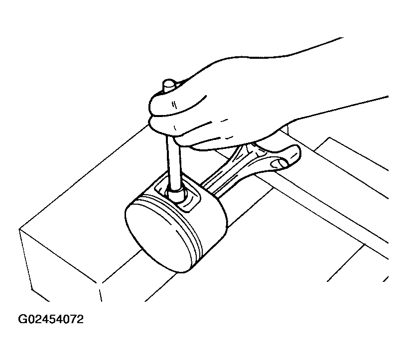 Courtesy of NISSAN MOTOR CO., U.S.A.
- Remove the lower cylinder block bolts.
- Before loosening the lower cylinder block bolts, measure the crankshaft side clearance. Refer to CRANKSHAFT SIDE CLEARANCE .
- Loosen them in the order shown to remove them.
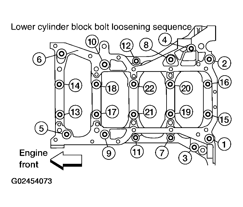 Courtesy of NISSAN MOTOR CO., U.S.A.
- Remove the lower cylinder block.
- Using Tool cut the Silicone RTV Sealant and remove the lower cylinder block from the cylinder block.
- Tool number: KV10111100 (J-37228)
CAUTION:
Be careful not to damage the mounting surface.
- Remove the crankshaft.
CAUTION:
- Do not damage or deform the signal plate while mounted on the crankshaft.
- When setting the crankshaft on a flat surface, use a block of wood to avoid interference between the signal plate and the surface.
- Do not remove signal plate unless it is necessary.
- Pull the rear oil seal out of the rear end of the crankshaft using suitable tool.
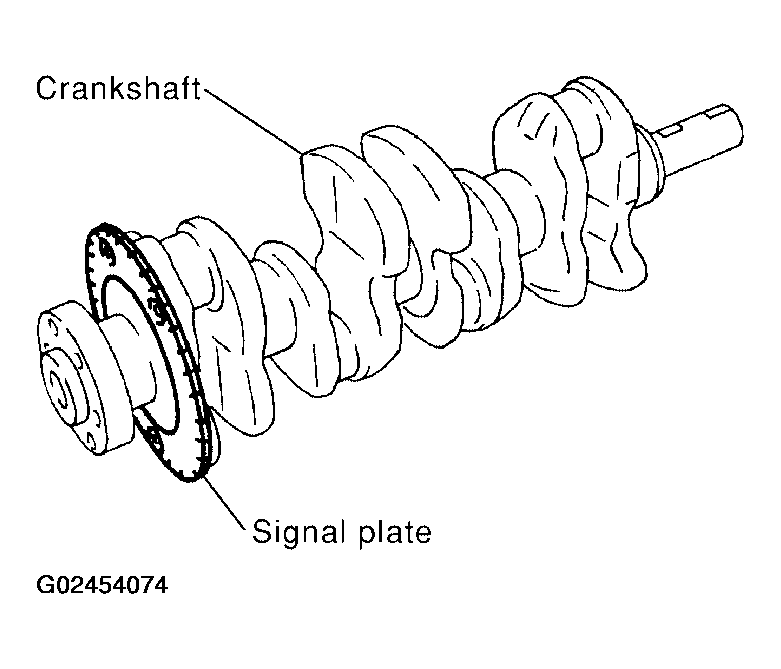 Courtesy of NISSAN MOTOR CO., U.S.A.
CAUTION:
Do not to damage the crankshaft or cylinder block when removing the rear oil seal.
NOTE:
When replacing the rear oil seal without removing the cylinder block, use a screwdriver to pull it out from between crankshaft and block.
- Remove the main bearings and thrust bearings from the cylinder block and lower cylinder block.
CAUTION:
Identify and number the bearings, if reusing them, so that they are assembled in the same position and direction.