- Release the fuel pressure. Refer to FUEL PRESSURE CHECK
.
- Remove the battery.
- Drain the engine cooling system.
- Drain engine oil. Refer to CHANGING ENGINE OIL
.
- Remove engine cover with power tool.
- Remove the intake air duct with the air cleaner case lid and mass air flow sensor.
- Remove the engine coolant reservoir.
- Disconnect the fuel rail quick connector at the vehicle piping side. Refer to Removal and Installation .
- Remove the cowl top grille and the windshield wiper assembly. Refer REMOVAL AND INSTALLATION
, REMOVAL AND INSTALLATION OF WIPER MOTOR AND LINKAGE
.
- Remove the front RH wheel and tire with power tool.
- Remove the engine undercovers with power tool.
- Remove the inner fender splash shield with power tool.
- Remove the drive belts and idler pulley.
- Recover the A/C system R134a and remove the A/C compressor. Refer to HFC-134A (R-134A) SERVICE PROCEDURE
, REMOVAL AND INSTALLATION FOR COMPRESSOR -- VQ35DE MODELS
.
- Dismount the power steering oil pump and reservoir tank. Tie them down with wire to reposition them out of the way.
- Remove the lower and upper oil pans. Refer to Removal and Installation .
- Remove the A/C high pressure line. Refer to REMOVAL AND INSTALLATION FOR HIGH-PRESSURE PIPE
.
- Remove the alternator. Refer to REMOVAL AND INSTALLATION
.
- Disconnect the engine harness and set aside.
- Support the engine and remove the RH engine mount and bracket.
- Remove the IVT control covers, right and left. Loosen the bolts in the numerical order as shown.
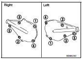 Courtesy of NISSAN MOTOR CO., U.S.A.
NOTE:
The shaft in the cover is inserted into the center hole of the intake camshaft sprocket. Remove the cover by pulling straight out until the cover disengages from the camshaft sprocket.
- Remove the starter motor. Refer to STARTER
.
- Obtain compression TDC of No. 1 cylinder as follows:
- Rotate crankshaft pulley clockwise to align pointer (A) with TDC mark on crankshaft pulley.
 Courtesy of NISSAN MOTOR CO., U.S.A.
- Check that intake and exhaust cam nose on No. 1 cylinder (engine front side of right) are located as shown.
- If not, turn the crankshaft one revolution (360°) and align as shown.
 Courtesy of NISSAN MOTOR CO., U.S.A.
- Set the ring gear stopper using the mounting bolt hole.
CAUTION:
Do not damage the ring gear teeth, or the signal plate teeth behind the ring gear, when setting the stopper.
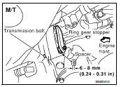 Courtesy of NISSAN MOTOR CO., U.S.A.
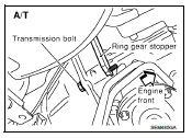 Courtesy of NISSAN MOTOR CO., U.S.A.
- Remove the crankshaft pulley as follows:
- Set the ring gear stopper using the mounting bolt hole.
CAUTION:
Do not damage the ring gear teeth, or the signal plate teeth behind the ring gear, when setting the stopper.
Courtesy of NISSAN MOTOR CO., U.S.A.
Courtesy of NISSAN MOTOR CO., U.S.A.
- Loosen crankshaft pulley mounting bolt using pulley holder and locate bolt seating surface at 10 mm (0.39 in) from its original position.
 Courtesy of NISSAN MOTOR CO., U.S.A.
- Position a pulley puller at recess hole of crankshaft pulley to remove crankshaft pulley.
CAUTION:
Do not use a puller claw on crankshaft pulley periphery.
 Courtesy of NISSAN MOTOR CO., U.S.A.
- Remove the front timing chain case.
- Loosen the bolts in the numerical order as shown.
 Courtesy of NISSAN MOTOR CO., U.S.A.
- Insert the suitable tool (2) into the notch (1) at the top of the front timing chain case as shown
- Pry off the case by moving the suitable tool (2) as shown.
 Courtesy of NISSAN MOTOR CO., U.S.A.
- Use seal cutter or an equivalent tool to cut liquid gasket for removal.
CAUTION:
- Do not use a screwdriver or similar tool.
- After removal, handle carefully so it does not bend, or warp under a load.
- Disconnect the power brake booster vacuum hose.
- Disconnect the electric throttle control actuator.
- Disconnect the coolant hoses at the electric throttle control actuator.
- Disconnect the PCV hose.
- Disconnect the EVAP canister purge volume control solenoid vacuum hose.
- Remove the intake manifold collector. Loosen the bolts and nuts in the numerical order as shown.
 Courtesy of NISSAN MOTOR CO., U.S.A.
- Remove the six ignition coils.
 Courtesy of NISSAN MOTOR CO., U.S.A.
- Remove the six spark plugs.
- Remove the engine oil dipstick.
- Remove the IVT control solenoid valves.
NOTE:
Discard the gasket and use new gaskets for installation.
 Courtesy of NISSAN MOTOR CO., U.S.A.
- Remove the rocker covers. Loosen the bolts in the numerical order as shown.
 Courtesy of NISSAN MOTOR CO., U.S.A.
- Place paint marks on the timing chain and sprockets to indicate the correct position of the components for installation.
- Remove the internal chain guide.
 Courtesy of NISSAN MOTOR CO., U.S.A.
- Remove the timing chain tensioner and slack guide.
- Pull lever down and release plunger stopper tab. Plunger stopper tab can be pushed up to release (coaxial structure with lever).
- Insert stopper pin into tensioner body hole to hold lever, and keep the tab released. An Allen wrench [2.5 mm (0.098 in)] is used for a stopper pin as an example
 Courtesy of NISSAN MOTOR CO., U.S.A.
- Insert plunger into tensioner body by pressing the slack side chain guide.
- Keep the slack guide pressed and hold it by pushing the stopper pin through the lever hole and body hole.
 Courtesy of NISSAN MOTOR CO., U.S.A.
- Remove the bolts and remove the timing chain tensioner.
- Remove primary timing chain and crankshaft sprocket.
CAUTION:
After removing timing chain, do not turn the crankshaft and camshaft separately, or the valves will strike the pistons.
- Attach a suitable stopper pin to the right and left camshaft chain tensioners (for secondary timing chains).
 Courtesy of NISSAN MOTOR CO., U.S.A.
- Remove the intake and exhaust camshaft sprocket bolts.
- Apply paint to the timing chain and camshaft sprockets for alignment during installation.
- Secure the hexagonal portion of the camshaft using a wrench to loosen the bolts.
 Courtesy of NISSAN MOTOR CO., U.S.A.
- Remove the secondary timing chains with camshaft sprockets.
- Rotate camshaft slightly, and slacken timing chain of timing chain tensioner side.
- Insert metal or resin plate [0.5 mm (0.020 in)] into guide between timing chain and chain tensioner plunger. Remove camshaft sprocket and secondary timing chain with timing chain removed from guide groove.
 Courtesy of NISSAN MOTOR CO., U.S.A.
CAUTION:
Chain tensioner plunger can move, while stopper pin is inserted in tensioner. Plunger can come out of tensioner when timing chain is removed. Use caution during removal.
- Intake camshaft sprocket is two-for-one structure of primary and secondary sprockets.
- Handle the intake sprockets as an assembly.
CAUTION:
- Avoid impact or dropping the intake sprockets.
- Do not disassemble the intake sprockets (never loosen bolts A and B as shown).
 Courtesy of NISSAN MOTOR CO., U.S.A.
- Remove the chain tension guide.
- Rremove the rear timing chain case.
CAUTION:
- Do not remove the plate metal cover for the oil passage.
 Courtesy of NISSAN MOTOR CO., U.S.A.
- After removing the chain case, do not apply any load to the case that might bend it.
- Loosen and remove the rear timing chain case bolts in the order shown.
 Courtesy of NISSAN MOTOR CO., U.S.A.
- Cut the sealant with an appropriate tool and remove the rear timing chain case.
- Remove O-rings on the cylinder head and cylinder block.
- Use a scraper to remove all of the old Silicone RTV Sealant from the front and rear timing chain case and opposite mating surfaces.
CAUTION:
Do not damage the mating surfaces
 Courtesy of NISSAN MOTOR CO., U.S.A.
- Remove all old Silicone RTV Sealant from all the bolt holes and bolts.
CAUTION:
Do not damage the threads or mating surfaces.
 Courtesy of NISSAN MOTOR CO., U.S.A.
- Use a scraper to remove all the old Silicone RTV Sealant from the water pump cover, chain tensioner cover and IVT control covers.
CAUTION:
Do not damage the mating surfaces
 Courtesy of NISSAN MOTOR CO., U.S.A.
- Remove the front oil seal from the front timing chain case using a suitable tool.
CAUTION:
Do not damage the front cover.
 Courtesy of NISSAN MOTOR CO., U.S.A.