Control Valve Assembly: Assembly: Notes
- Install upper, inter and lower body.
- Place oil circuit of upper body face up. Install steel balls in their proper positions.
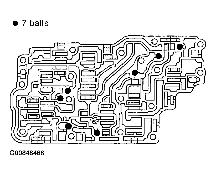 Courtesy of NISSAN MOTOR CO., U.S.A.
- Install upper separating gasket, upper inter separating gasket and upper separating plate in order shown in illustration.
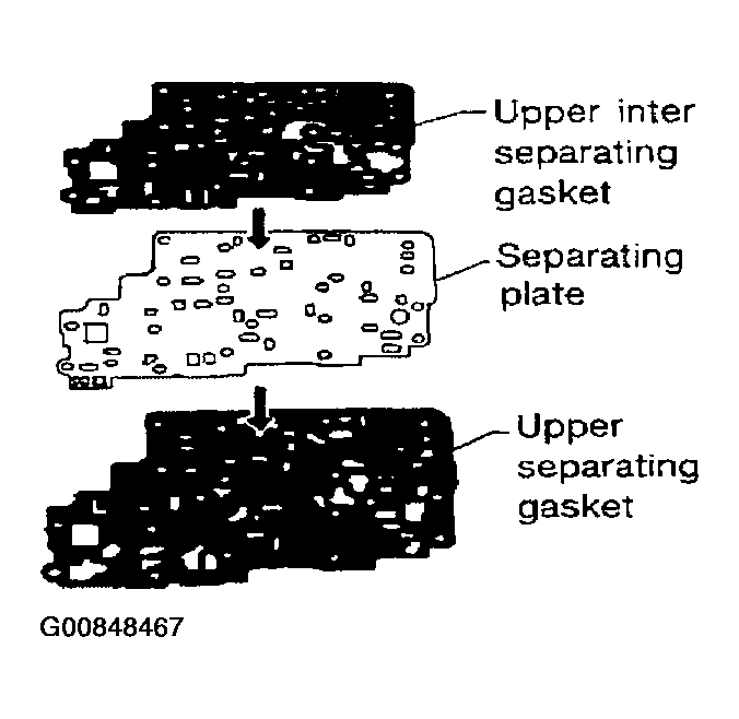 Courtesy of NISSAN MOTOR CO., U.S.A.
- Install reamer bolts f
from bottom of upper body. Using reamer bolts as guides, install separating plate and gaskets as a set.
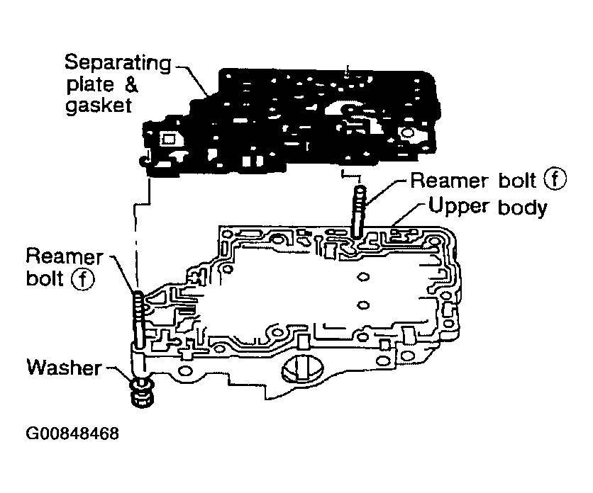 Courtesy of NISSAN MOTOR CO., U.S.A.
- Install pilot filter.
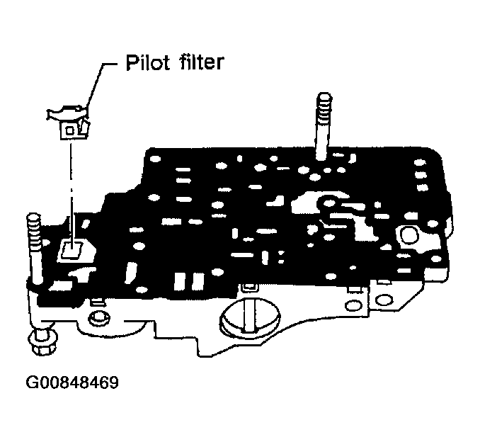 Courtesy of NISSAN MOTOR CO., U.S.A.
- Place lower body as shown in illustration (side of inter body face up). Install steel balls in their proper positions.
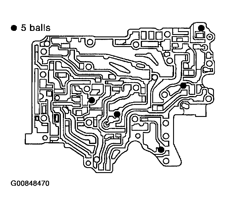 Courtesy of NISSAN MOTOR CO., U.S.A.
- Install inter body on upper body using reamer bolts f
as guides.
- Be careful not to dislocate or drop steel balls.
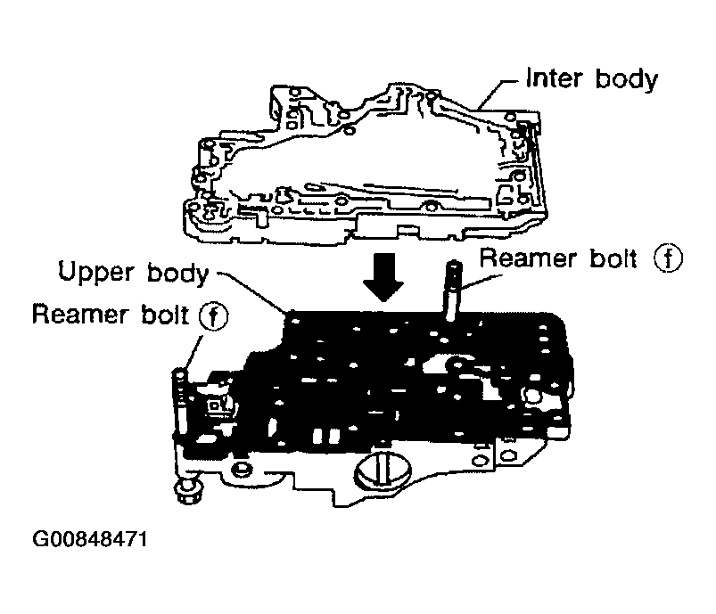 Courtesy of NISSAN MOTOR CO., U.S.A.
- Install check balls and oil cooler relief valve springs in their proper positions in lower body.
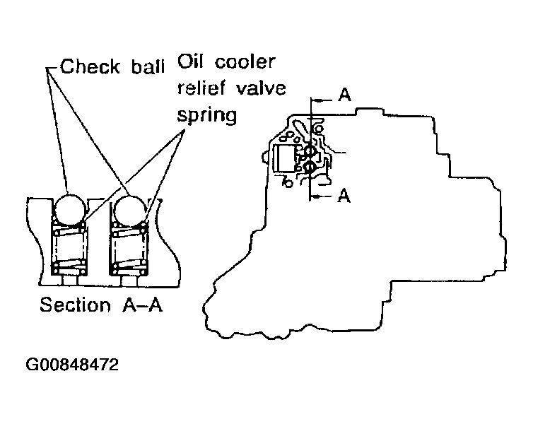 Courtesy of NISSAN MOTOR CO., U.S.A.
- Install lower separating gasket, lower inter separating gasket and lower separating plate in order shown in illustration.
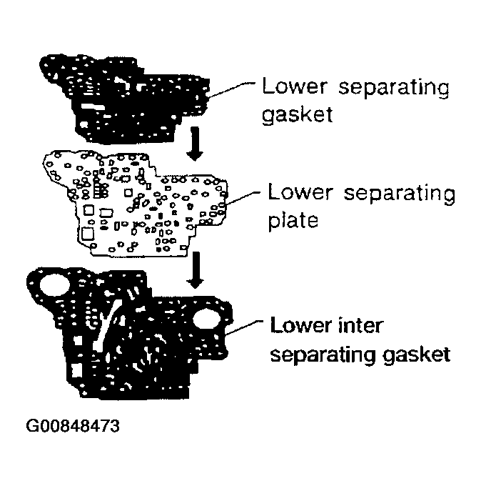 Courtesy of NISSAN MOTOR CO., U.S.A.
- Install bolts e
from bottom of lower body. Using bolts e
as guides, install separating plate and gaskets as a set.
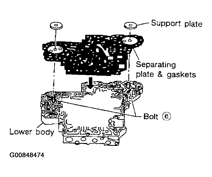 Courtesy of NISSAN MOTOR CO., U.S.A.
- Temporarily install support plates on lower body.
- Install lower body on inter body using reamer bolts f
as guides and tighten reamer bolts f
slightly.
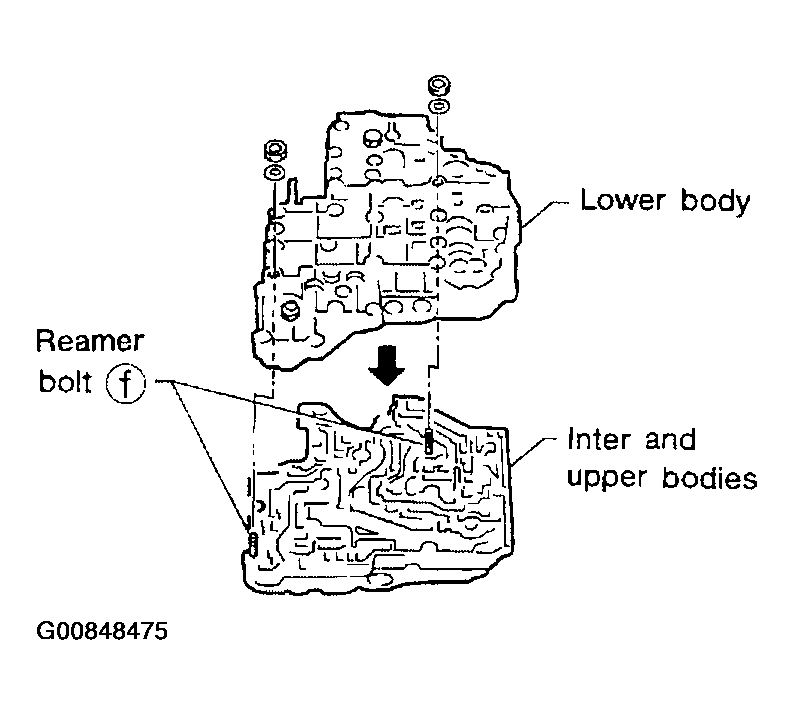 Courtesy of NISSAN MOTOR CO., U.S.A.
- Install O-rings to solenoid valves and terminal body.
- Apply ATF to O-rings.
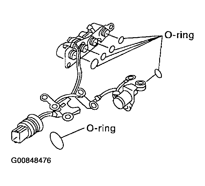 Courtesy of NISSAN MOTOR CO., U.S.A.
- Install and tighten bolts.